Chrysler Crossfire. Manual - part 783


  Index      Chrysler     Chrysler Crossfire - service repair manual 2005 year


Search            


Content   ..  781  782  783  784   ..


Chrysler Crossfire. Manual - part 783


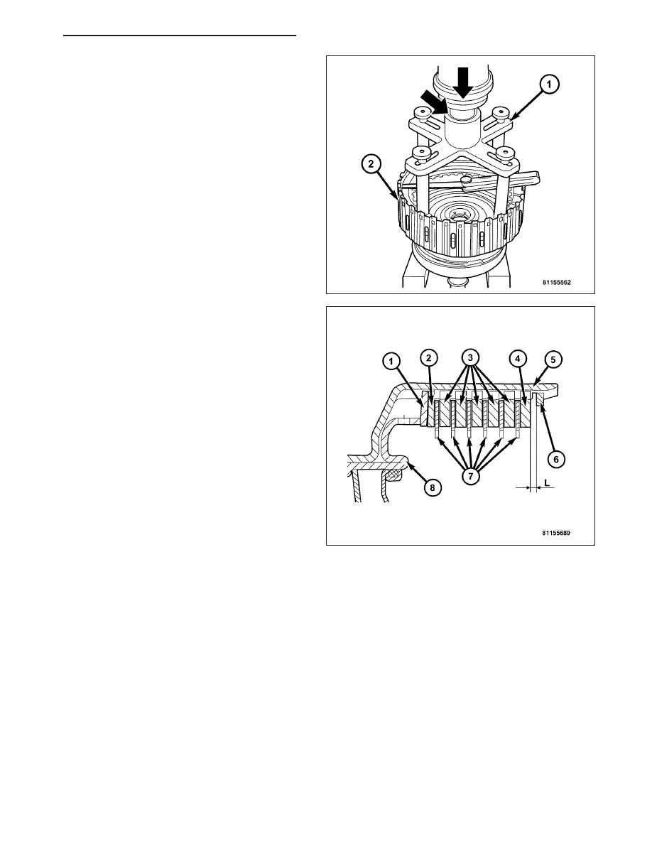
a. Mount Special Tool 8901 (1) on the outer disc

carrier.

b. Using a lever press, compress the pressing

tool as far as the stop (then the marking ring is
still visible, see small arrow).

c. Using a feeler gauge, determine the play “L” at

three points between the snap-ring (8) and
outer multiple-disc (2).

d. During the measurement, the snap-ring must

contact the upper bearing surface of the
groove in the outer multiple-disc carrier.

e. The correct clutch clearance is 2.3-2.7 mm

(0.091-0.106 in.) for three friction disc versions,
2.4-2.8 mm (0.095-0.110 in.) for four disc ver-
sions, and 2.5-2.9 mm (0.099-0.114 in.) for five
disc versions.

f. Adjust with snap-ring, if necessary. Snap-rings

are available in thicknesses of 2.0 mm (0.079
in.), 2.3 mm (0.091 in.), 2.6 mm (0.102 in.), 2.9
mm (0.114 in.), 3.2 mm (0.126 in.), and 3.5 mm
(0.138 in.).

ELECTROHYDRAULIC UNIT

DESCRIPTION

The electrohydraulic control unit comprises the shift plate made from light alloy for the hydraulic control and an
electrical control unit. The electrical control unit comprises of a supporting body made of plastic, into which the
electrical components are assembled. The supporting body is mounted on the shift plate and screwed to it.

Strip conductors inserted into the supporting body make the connection between the electrical components and a
plug connector. The connection to the wiring harness on the vehicle and the transmission control module (TCM) is
produced via this 13-pin plug connector with a bayonet lock.

ZH

AUTOMATIC - NAG1 SERVICE INFORMATION

21 - 281

ELECTRICAL CONTROL UNIT

The electrical control unit (7) consists of a plastic shell
which houses the RPM sensors (1,12), regulating
solenoid valves (3, 4), solenoid valves (5, 6, 10), the
TCC solenoid valve (11), the park/neutral contact (9),
and the transmission oil temperature sensor (8). Con-
ductor tracks integrated into the shell connect the
electric components to a plug connection (2). This
13-pin plug connection (2) establishes the connection
to the vehicle-side cable harness and to the transmis-
sion control module (TCM). With the exception of the
solenoid valves, all other electric components are
fixed to the conductor tracks.

HYDRAULIC CONTROL UNIT

Working Pressure (Operating Pressure) (p-A)

The working pressure provides the pressure supply to the hydraulic control and the transmission shift elements. It is
the highest hydraulic pressure in the entire hydraulic system. The working pressure is regulated at the working pres-
sure regulating valve in relation to the load and gear. All other pressures required for the transmission control are
derived from the working pressure.

Lubrication Pressure (p-Sm)

At the working pressure regulating valve, surplus oil is diverted to the lubrication pressure regulating valve, from
where it is used in regulated amounts to lubricate and cool the mechanical transmission components and the torque
converter. Furthermore, the lubrication pressure (p-Sm) is also used to limit the pressure in the torque converter.

Shift Pressure (p-S)

The shift pressure is determined by the shift pressure regulating solenoid valve and the shift pressure regulating
valve. The shift pressure:

Regulates the pressure in the activating shift element during the shift phase.

Determines, together with the modulating pressure, the pressure reduction at the deactivating shift element as
regulated by the overlap regulating valve.

Initializes 2nd gear in limp-home mode.

Modulating Pressure (p-Mod)

The modulating pressure influences the size of the working pressure and determines, together with the shift pres-
sure, the pressure regulated at the overlap regulating valve. The modulating pressure is regulated at the modulating
pressure regulating solenoid valve, which is under regulating valve pressure. The modulating pressure is variable
and relative to the engine load.

Regulating Valve Pressure (p-RV)

The regulating valve pressure is regulated at the regulating valve pressure regulating valve in relation to the working
pressure (p-A) up to a maximum pressure of 8 bar (116 psi). It supplies the modulating pressure regulating solenoid
valve, the shift pressure regulating solenoid valve and the shift valve pressure regulating valve.

21 - 282

AUTOMATIC - NAG1 SERVICE INFORMATION

ZH

Shift Valve Pressure (p-SV)

The shift valve pressure (p-SV) is derived from the regulating valve pressure (p-RV), is regulated at the shift valve
pressure regulating valve and is then present at the:

1-2 and 4-5 shift solenoid valve.

3-4 shift solenoid valve.

2-3 shift solenoid valve.

Torque converter lockup solenoid valve.

3-4 and 2-3 shift pressure shift valve.

The shift valve pressure (p-SV) controls the command valves via the upshift/downshift solenoid valves.

Overlap Pressure (p-Ü)

The overlap pressure controls the shift component pressure reduction during a shift phase. The pressure in a shift
element as it disengages is controlled during the shift phase depending on engine load (modulating pressure) and
the pressure in the shift element as it engages. The adjusted pressure is inversely proportional to the transmission
capability of the shift element being engaged (controlled overlap).

Working Pressure Regulating Valve (Operating Pressure)

The working pressure regulating valve (4) is located in
the valve housing of the shift plate. It regulates the pri-
mary pressure of the hydraulic system.

ZH

AUTOMATIC - NAG1 SERVICE INFORMATION

21 - 283

Torque Converter Lockup Clutch Regulating Valve

The torque converter lock-up clutch regulating valve
(6) is located in the valve housing of the electrohy-
draulic control module. The valve is responsible for the
hydraulic control of the torque converter lockup clutch
and distribution of the lubricating oil.

Overlap Regulating Valve

Each shift group is assigned one overlap regulating
valve (1). The 1-2 / 4-5 overlap regulating valve is
installed in the shift valve housing; the 2-3 and 3-4
overlap regulating valves are installed in the valve
housing. The overlap regulating valve regulates the
pressure reduction during a shift phase.

21 - 284

AUTOMATIC - NAG1 SERVICE INFORMATION

ZH


Content   ..  781  782  783  784   ..