Chrysler Crossfire. Manual - part 766


  Index      Chrysler     Chrysler Crossfire - service repair manual 2005 year


Search            


Content   ..  764  765  766  767   ..


Chrysler Crossfire. Manual - part 766


Gear Shift N to D (1st gear) - Engine Started

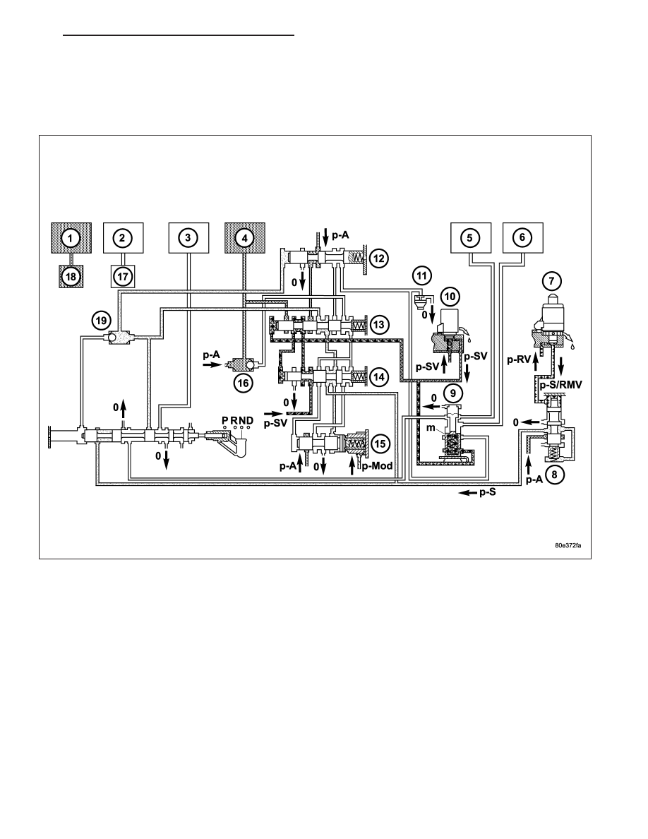
With the engine started and the gearshift lever in the NEUTRAL or PARK positions, holding clutch B1 (1) and driving
clutch K3 (4) are applied and the various valves in the 1-2/4-5 shift group are positioned to apply pressure to the
multi-disc holding clutch B2.

ZH

AUTOMATIC - NAG1 SERVICE INFORMATION

21 - 213

Activation Sequence

The selector valve opens the shift pressure (p-S) feed connection from the ball valve (19) with the shift valve B2 (9).
With the shift valve B2 (9) in the upper position, shift pressure (p-S) travels behind the piston B2 (5) and simulta-
neously to the opposing face of the piston B2 (6). The multi-disc holding clutch B2 begins to close.

The pressure on the opposing face of the piston B2 (6) ensures a soft activation of the multi-disc holding clutch B2.

21 - 214

AUTOMATIC - NAG1 SERVICE INFORMATION

ZH

First Gear Engaged

The TCM monitors the activation sequence via the speed of the input shaft, which slows down as the frictional
connection in the multiple-disc holding clutch increases. When the speed drops to the specified level, the TCM shuts
off the power to the 3-4 shift solenoid (10). The spring chamber of the shift valve B2 (9) is depressurized and
switches downwards. This connects the line to the opposing face of the piston B2 (6) with the pressure holding
valve (11). The pressure on the opposing face of the piston B2 (6) drops to a residual pressure.

The working pressure (p-A) is formed and travels via the 2-3 holding pressure shift valve, the 2-3 command valve
and the ball valve (16) to driving clutch K3 (4) and via the 3-4 command valve (13) to the end face of the 3-4 shift
pressure shift valve (14). The 3-4 shift pressure shift valve (14) is moved against the force of the spring towards the
right. At the same time the 3-4 solenoid valve (10) is energized. This allows shift valve pressure (p-SV) to enter the
spring chamber of the shift valve B2 (9) and to reach the end face of the 3-4 command valve (13). The shift valve
B2 (9) is held in the upper position and the 3-4 command valve (13) switches towards the right. At the end face of
the 3-4 shift pressure shift valve (14) the working pressure (p-A) is replaced by shift valve pressure (p-SV).

The 3-4 command valve (13) moves to the left. Working pressure (p-A) travels via the holding pressure shift valve
(12) and the 3-4 command valve (13) to the piston of multi-disc holding clutch B2 (5).

ZH

AUTOMATIC - NAG1 SERVICE INFORMATION

21 - 215

DIAGNOSIS AND TESTING

AUTOMATIC TRANSMISSION

CAUTION: Before attempting any repair on a NAG1 automatic transmission, check for Diagnostic Trouble
Codes with the DRBIII

T

scan tool.

Transmission malfunctions may be caused by these general conditions:

Poor engine performance.

Improper adjustments.

Hydraulic malfunctions.

Mechanical malfunctions.

Electronic malfunctions.

Transfer case performance.

Diagnosis of these problems should always begin by checking the easily accessible variables: fluid level and con-
dition, gearshift cable adjustment. Then perform a road test to determine if the problem has been corrected or if
more diagnosis is necessary.

DIAGNOSIS AND TESTING - PRELIMINARY

IF VEHICLE IS DRIVEABLE

1. Check for transmission fault codes using the DRBIII

T

scan tool.

2. Check the fluid level and its condition.

3. Adjust the gearshift cable if the complaint was based on delayed, erratic, or harsh shifts.

4. Road test the vehicle and note how the transmission upshifts, downshifts, and engages.

IF VEHICLE IS DISABLED

1. Check the fluid level and its condition.

2. Check for a broken or disconnected gearshift cable.

3. Check for a cracked or leaking cooler line, loose or missing pressure-port plugs.

4. Raise and support the vehicle on safety stands, start the engine, shift the transmission into gear, and note the

following:

a. If the propeller shaft turns but the wheels do not, inspect the differential and axle shafts.

b. If the propeller shaft does not turn and the transmission is noisy, stop the engine. Remove the transmission

oil pan, and check for debris. If the pan is clear, remove the transmission and check for a damaged flexplate,
torque converter, oil pump, or input shaft.

c. If the propeller shaft does not turn and the transmission is not noisy, perform the hydraulic-pressure test to

determine if the concern is hydraulic or mechanical.

DIAGNOSIS AND TESTING - ROAD TESTING

Before road testing the vehicle, be sure that the fluid level and the control cable adjustments have been checked
and adjusted if necessary. Verify that all the diagnostic trouble codes have been resolved.

Observe the engine’s performance during the road test. A poorly tuned engine will not allow an accurate analysis of
the transmission’s operation.

Operate the transmission in all gear ranges. Check for shift variations and engine flare which indicates slippage.
Note if shifts are harsh, spongy, delayed, early, or if part throttle downshifts are sensitive.

Slippage is indicated by engine flare, this usually means that the transmission has a clutch concern an overrunning
clutch or a possible line pressure problem.

A slipping clutch can often be determined by comparing which internal units are applied in various gear ranges. The
clutch application chart provides a basis for analyzing road test results.

21 - 216

AUTOMATIC - NAG1 SERVICE INFORMATION

ZH


Content   ..  764  765  766  767   ..