Index Chrysler Chrysler Crossfire - service repair manual 2005 year
Search
Content .. 743 744 745 746 ..
Chrysler Crossfire. Manual - part 745
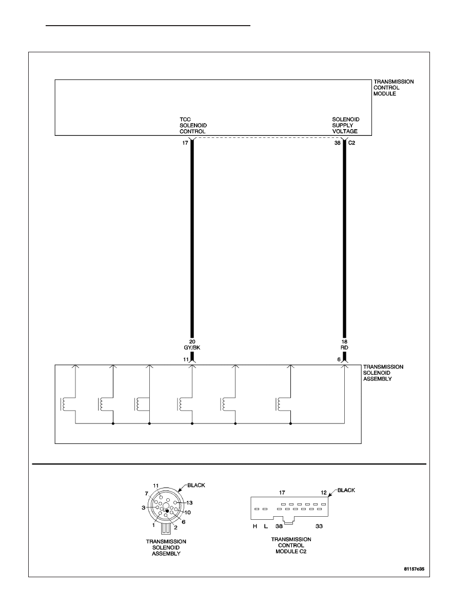
(P0743) TCC SOLENOID CIRCUIT
ZH
NAG1 - ELECTRICAL DIAGNOSTICS
21 - 129