Chrysler Crossfire. Manual - part 716
(P0600) ABS BRAKE MESSAGE (CONTINUED)
When Monitored and Set Condition
•
When Monitored: Valid ABS CAN BUS message received at least once and CAN BUS Circuit, ABS CAN Mes-
sage Missing, ABS CAN Message Incorrect are not active.
•
Set Condition: Brake light switch signal not valid - CAB sending invalid value.
POSSIBLE CAUSES
CAN BUS CIRCUIT DTC PRESENT
ABS DTCS PRESENT
CONTROLLER ANTILOCK BRAKE
TRANSMISSION CONTROL MODULE
For a complete Transmission Control Module Circuit Diagram, (Refer to 21 - TRANSMISSION/TRANSAXLE/AUTO-
MATIC - NAG1 - SCHEMATICS AND DIAGRAMS).
For a complete CAN BUS Circuit Diagram, (Refer to 8 - ELECTRICAL/ELECTRONIC CONTROL MODULES -
SCHEMATICS AND DIAGRAMS).
Diagnostic Test
1.
PRE-DIAGNOSTIC CHECK OUT
Note: Low fluid level can be the cause of many transmission
problems. If the fluid level is low, locate and repair the leak then
check and adjust the fluid level in accordance with the Service
Information.
Note: Always perform diagnostics with a fully charged battery to
avoid false symptoms.
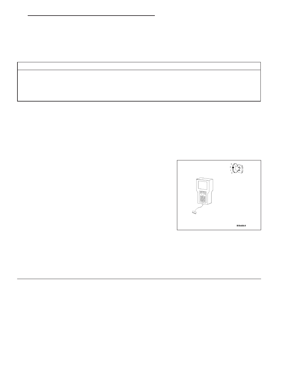
With the DRB III
T
, read Engine DTCs. Check and repair all engine
DTCs prior to performing transmission symptom diagnostics.
With the DRB III
T
, read and record all Transmission DTCs.
Note: Check connectors - Clean/repair as necessary. Poor pin to
terminal connections can set DTCs.
Using the wiring diagram/schematic as a guide, inspect the wiring and
connectors. Repair as necessary.
Most DTCs set on start up but some must be set by driving the vehicle such that all diagnostic monitors have run.
Note: Check for any Technical Service Bulletins that may apply.
Perform this procedure prior to Symptom diagnosis.
Continue
Go To 2
ZH
NAG1 - ELECTRICAL DIAGNOSTICS
21 - 13