Chrysler Crossfire. Manual - part 706


  Index      Chrysler     Chrysler Crossfire - service repair manual 2005 year


Search            


Content   ..  704  705  706  707   ..


Chrysler Crossfire. Manual - part 706


INSTALLATION - RHD

1. Turn the steering gear to the center position by

aligning the marking lines on the steering shaft and
the housing cover.

CAUTION: DO NOT use force, otherwise the lower
steering shaft (collapsible tubing) will be dam-
aged. Insure that the connection is assembled cor-
rectly.

2. Carefully install the steering gear coupling onto the

steering shaft.

3. Push the lower steering shaft into the steering cou-

pling then tighten the steering gear pinch bolt.
Tighten to 60 N·m (44 ft. lbs.).

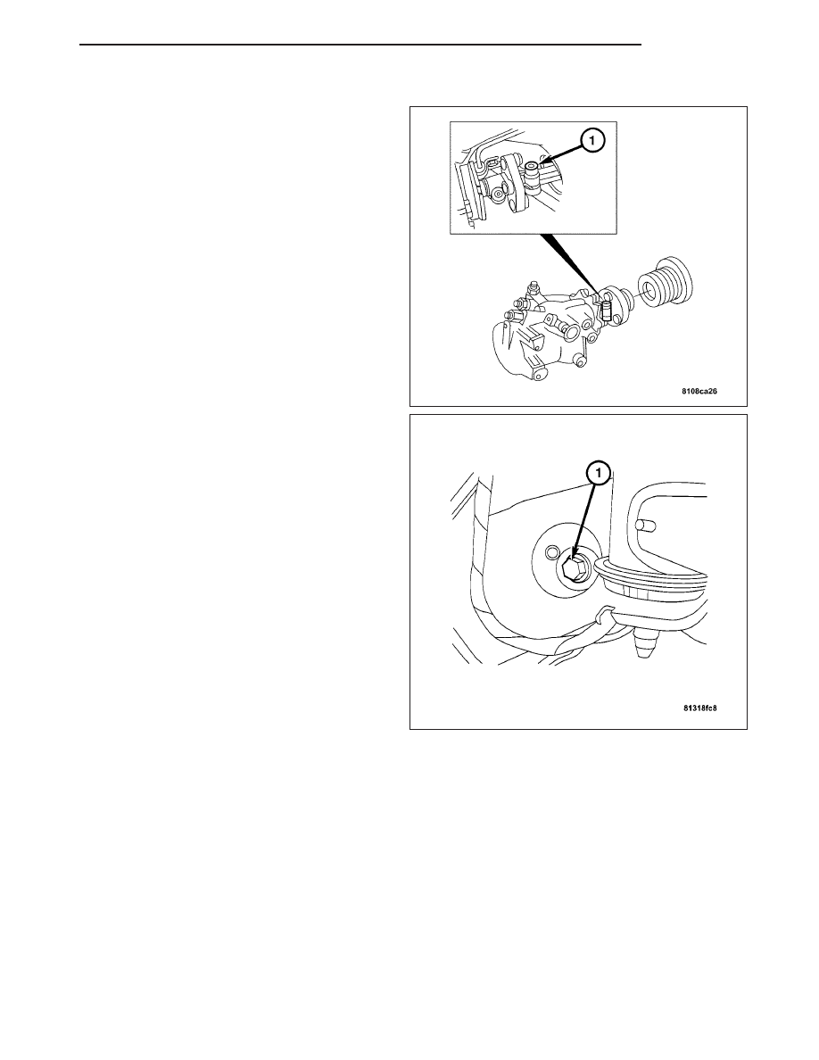
4. Lower the engine and install the engine mount

bolts (1). Tighten to 25 N·m (18 ft. lbs.).

5. Install the ground strap to the frame.

ZH

GEAR

19 - 43

6. Install the pinch bolt (1) to the steering coupling.

Tighten to 16-20 N·m (11-15 ft. lbs.).

7. Install the high-pressure hose (2). Tighten to 30

N·m (22 ft. lbs.).

8. Install the return line (3). Tighten to 40 N·m (30 ft.

lbs.).

9. Install the drag link/tie rod. (Refer to 19 - STEER-

ING/LINKAGE/DRAG LINK - INSTALLATION).

10. Install the right front cross brace.

11. Fill and bleed the power steering pump. (Refer to

19

-

STEERING/PUMP

-

STANDARD

PROCEDURE).

19 - 44

GEAR

ZH

ADJUSTMENTS

STEERING GEAR

1. Using Special Tool 9168 Ball Joint Puller (2)

remove the drag link/tie rod at the pitman arm (1).
(Refer to 19 - STEERING/LINKAGE/DRAG LINK -
REMOVAL).

2. Determine the friction torque of the steering gear

by slowly turning the steering wheel from stop to
stop several times.

3. Adjust the steering gear by loosening the lock nut.

4. Turn the adjusting screw 1/4 revolutions in stages.

Counterclockwise = less play = increased coeffi-
cient of friction.

Clockwise = more play = reduced coefficient of
friction.

5. Tighten the lock nut to 60 N·m (44 ft. lbs.).

6. Check the adjustment after tightening the lock nut,

repeat adjustment, if necessary.

PITMAN SHAFT SEAL

REMOVAL

1. Measure the distance of point “A” between the pit-

man arm (2) and the steering gear (1) using a cal-
iper gauge.

ZH

GEAR

19 - 45

2. Remove the lower snap ring (4) from the pitman

shaft.

3. Remove the pitman arm (3) from the pitman shaft.

4. Remove the upper locking ring (2).

5. Remove the pitman shaft seal (1) from the steering

gear housing using a suitable prying tool.

INSTALLATION

CAUTION: DO NOT damage the sealing lip of the
pitman shaft seal when sliding it on over the pit-
man shaft splines.

1. Using Special Tool 9159 Steering Seal Installer (1)

install a new pitman shaft seal into the steering
gear.

2. Install the upper snap ring (2).

3. Remove any oil and grease from the splined sec-

tion of the pitman arm, and the pitman arm shaft.

4. Install the lower snap ring (4).

19 - 46

GEAR

ZH


Content   ..  704  705  706  707   ..