Chrysler Crossfire. Manual - part 705


  Index      Chrysler     Chrysler Crossfire - service repair manual 2005 year


Search            


Content   ..  703  704  705  706   ..


Chrysler Crossfire. Manual - part 705


REMOVAL - RHD

1. Draw off the fluid from the power steering pump

reservoir.

2. Raise and support the vehicle.

3. Using special tool #9168, remove the drag link / tie

rod (1) from the pitman arm. (Refer to 19 - STEER-
ING/LINKAGE/DRAG LINK - REMOVAL).

4. Remove the right front body cross brace.

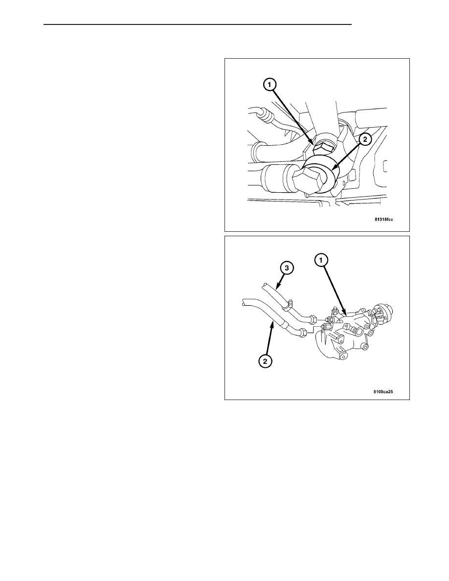
5. Remove the power steering return line (3) and the

high-pressure line (2).

6. Remove the ignition key and allow the steering

wheel to lock.

ZH

GEAR

19 - 39

7. Remove the pinch bolt (1) from the steering cou-

pling.

8. Remove the steering shaft from the steering gear.

9. Remove the engine ground strap from the frame

member.

10. Remove the lower engine mounting bolts (1) on

the left and right of the engine mounts.

11. Safely install a support jack (1) under the right

side of the engine. Raise the engine (2) approx.
40 mm (2 in.).

19 - 40

GEAR

ZH

12. Remove the three bolts (1), attaching the steering

gear to the body of the vehicle, carefully move
steering gear out of the steering shaft then
remove the steering gear from the vehicle.

INSTALLATION

INSTALLATION

1. Turn the steering gear to the center position by

aligning the marking lines on the steering shaft and
the housing cover.

CAUTION: DO NOT use force, otherwise the lower
steering shaft (collapsible tubing) will be dam-
aged. Ensure that the connection is assembled
correctly.

2. Carefully install the steering gear coupling onto the

steering shaft.

3. Push the lower steering shaft into the steering cou-

pling then bolt steering gear onto the vehicle.
Tighten to 60 N·m (44 ft. lbs.).

ZH

GEAR

19 - 41

4. Lower the engine and tighten the engine mounts

(1). Tighten to 25 N·m (18 ft. lbs.).

5. Install the ground strap to the frame.

6. Install the pinch bolt (1) to the steering coupling.

Tighten to 16-20 N·m (11-15 ft. lbs.).

7. Install the high-pressure hose (2). Tighten to 30

N·m (22 ft. lbs.).

8. Install the return line (3). Tighten to 40 N·m (30 ft.

lbs.).

9. Install the drag link/tie rod. (Refer to 19 - STEER-

ING/LINKAGE/DRAG LINK - INSTALLATION).

10. Install the left front cross brace.

11. Fill and bleed the power steering pump. (Refer to

19

-

STEERING/PUMP

-

STANDARD

PROCEDURE).

19 - 42

GEAR

ZH


Content   ..  703  704  705  706   ..