Chrysler Crossfire. Manual - part 704


  Index      Chrysler     Chrysler Crossfire - service repair manual 2005 year


Search            


Content   ..  702  703  704  705   ..


Chrysler Crossfire. Manual - part 704


GEAR

TABLE OF CONTENTS

page

page

GEAR

DESCRIPTION

. . . . . . . . . . . . . . . . . . . . . . . . . 35

OPERATION

. . . . . . . . . . . . . . . . . . . . . . . . . . . 35

REMOVAL

REMOVAL

. . . . . . . . . . . . . . . . . . . . . . . . . . . 36

REMOVAL - RHD

. . . . . . . . . . . . . . . . . . . . . . 39

INSTALLATION

INSTALLATION

. . . . . . . . . . . . . . . . . . . . . . . 41

INSTALLATION - RHD

. . . . . . . . . . . . . . . . . . 43

ADJUSTMENTS

STEERING GEAR

. . . . . . . . . . . . . . . . . . . . . 45

PITMAN SHAFT SEAL

REMOVAL

. . . . . . . . . . . . . . . . . . . . . . . . . . . . . 45

INSTALLATION

. . . . . . . . . . . . . . . . . . . . . . . . . 46
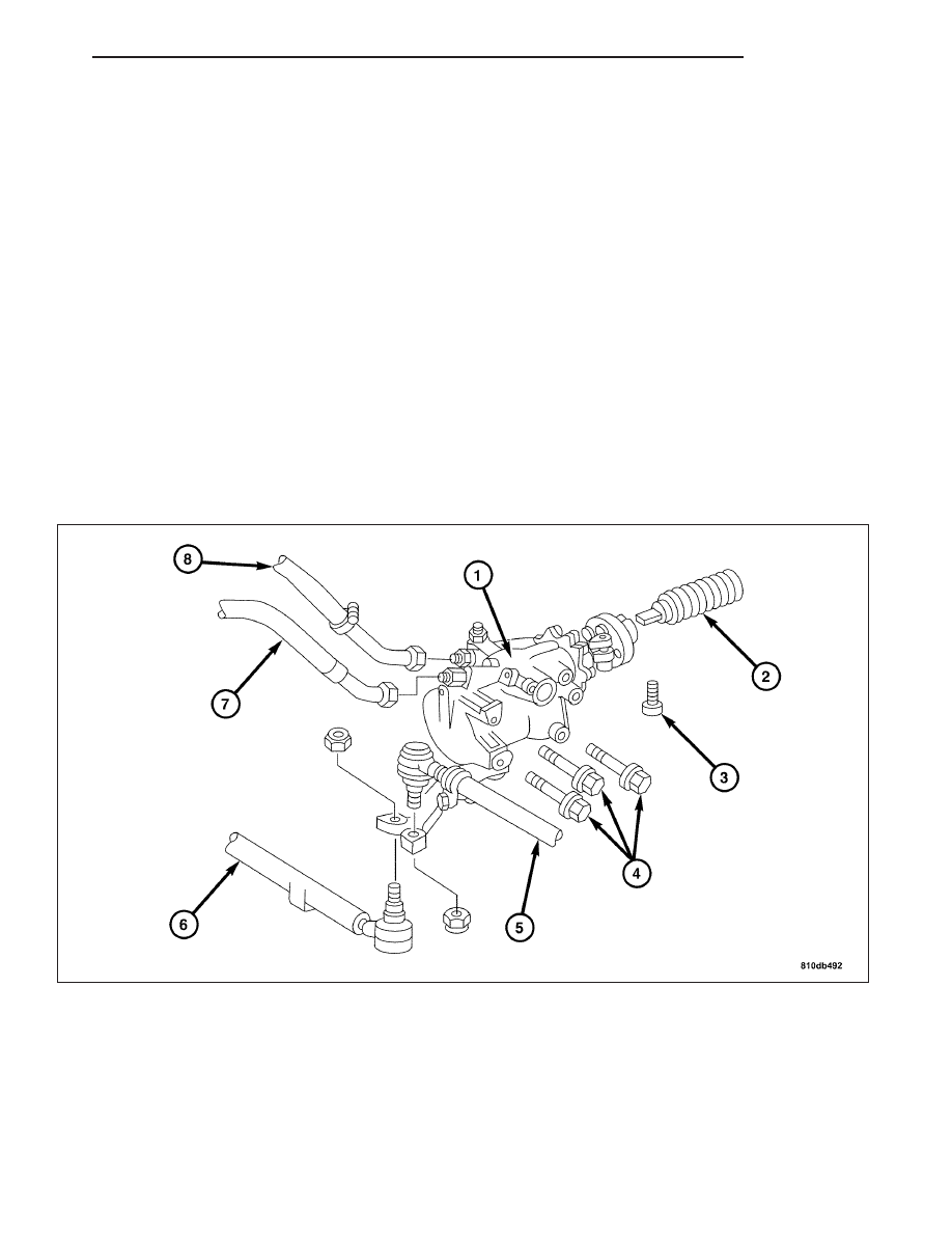
GEAR

DESCRIPTION

The Power Steering Gear is a recirculating ball type gear. The Steering Gear is securely mounted to the driver’s
side of the vehicle. The steering linkage is attached to the pitman arm then attached to the idler arm.

OPERATION

The Steering Gear acts as a rolling thread between the worm shaft and rack piston. The worm shaft is supported by
a thrust bearing at the lower end and a bearing assembly at the upper end. When the worm shaft is turned the rack
piston moves. The rack piston teeth mesh with the pitman shaft. Turning the worm shaft turns the pitman shaft,
which turns the steering linkage.

ZH

GEAR

19 - 35

REMOVAL

REMOVAL

1. Draw off the fluid from the power steering pump

reservoir.

2. Raise and support the vehicle.

3. Remove the drag link/tie rod (1) from the pitman

arm. (Refer to 19 - STEERING/LINKAGE/DRAG
LINK - REMOVAL).

4. Remove the left front cross brace.

19 - 36

GEAR

ZH

5. Remove the power steering return line (3) and the

high-pressure line (2).

WARNING: THE STEERING WHEEL MUST NOT BE
TURNED

WHEN

THE

STEERING

GEAR

IS

REMOVED,

OTHERWISE

THE

CLOCK

SPRING

CONTACT WILL BE DAMAGED BEYOND REPAIR.

6. Remove the ignition key and allow the steering

wheel to lock.

7. Remove the pinch bolt (1) from the steering cou-

pling.

8. Remove the steering shaft from the steering gear.

9. Remove the engine ground strap from the frame

member.

10. Remove the lower engine mounting bolts (1) on

the left and right of the engine mounts.

ZH

GEAR

19 - 37

11. Safely install a support jack (1), under the left side

of the engine. Raise the engine (2) approx. 40
mm (2 in.).

CAUTION: DO NOT use force, otherwise the lower
steering shaft will be damaged on vehicles with a
rigid steering column.

12. Remove the three bolts (1) attaching the steering

gear to the body of the vehicle, carefully move
steering gear out of the steering shaft then
remove the steering gear from the vehicle.

19 - 38

GEAR

ZH


Content   ..  702  703  704  705   ..