Chrysler Crossfire. Manual - part 693


  Index      Chrysler     Chrysler Crossfire - service repair manual 2005 year


Search            


Content   ..  691  692  693  694   ..


Chrysler Crossfire. Manual - part 693


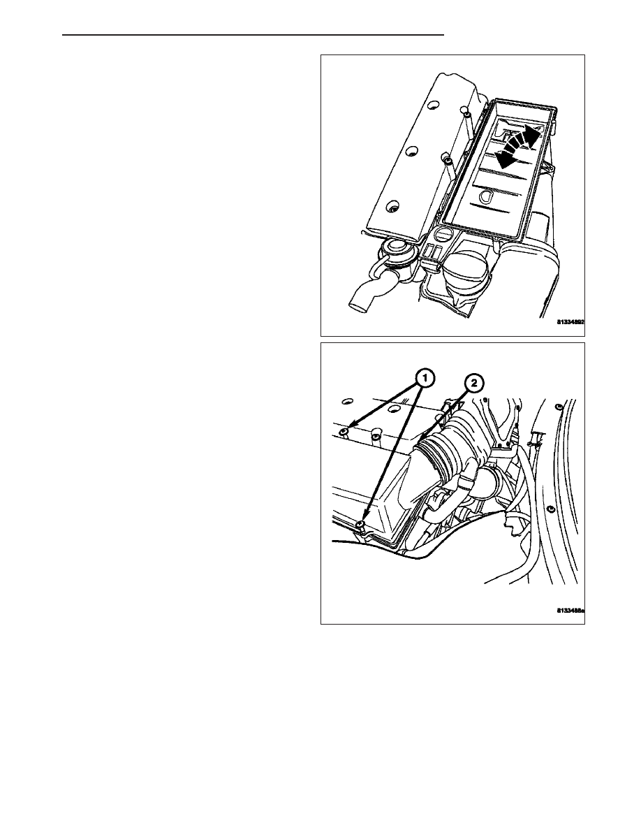
7. Install both right and left lower air cleaner hous-

ings. (Refer to 9 - ENGINE/AIR INTAKE SYSTEM/
AIR CLEANER HOUSING - INSTALLATION).

8. Install the upper air cleaner housings. (Refer to 9 -

ENGINE/AIR

INTAKE

SYSTEM/AIR

CLEANER

HOUSING - INSTALLATION).

9. Install the engine cover. Align the engine cover

retaining clips to the rubber mounts, and push
down firmly to connect engine cover to rubber
mounts.

Note: To ease the installation of the engine cover,
apply a small amount of lubricant to the engine
cover rubber mounts.

10. Connect the negative battery cable.

ZH

FUEL INJECTION

14 - 53

O2 SENSOR

DESCRIPTION

The Oxygen Sensors (O2S) are attached to, and protrude into the vehicle exhaust system. The vehicle uses a total
of 4 sensors; 2 upstream (referred to as 1/1 and 2/1) and 2 downstream (referred to as 1/2 and 2/2). The right
upstream sensor (1/1) is located in the right exhaust pipe just before the mini-catalytic converter. The left upstream
sensor (2/1) is located in the left exhaust pipe just before the mini-catalytic converter. The right downstream sensor
(1/2) is located in the right exhaust downpipe just after the mini-catalytic converter, and before the main catalytic
converter. The left downstream sensor (2/2) is located in the left exhaust downpipe just after the mini-catalytic con-
verter, and before the main catalytic converter.

OPERATION

An O2 Sensor is a galvanic battery that provides the Powertrain Control Module (PCM) with a voltage signal (0–1
Volt) inversely proportional to the amount of oxygen in the exhaust. In other words if the oxygen content is low, the
voltage output is high; if the oxygen content is high, the voltage output is low. The PCM uses this information to
adjust injector pulse-width to achieve the 14.7 to 1 air/fuel ratio necessary for proper engine operation and to control
emissions. The O2 Sensor must have a source of oxygen outside the exhaust stream for comparison. Current O2
Sensors receive their fresh oxygen (outside air) supply through the O2 Sensor case housing. Four wires (circuits)
are used on each O2 Sensor: a 12–Volt feed circuit for the sensor heating element, a ground circuit for the heater
element, a low-noise sensor return circuit to the PCM and an input circuit from the sensor back to the PCM to
detect sensor operation.

As vehicles accumulate mileage, the catalytic convertor deteriorates. The deterioration results in a less efficient cat-
alyst. To monitor catalytic convertor deterioration, the fuel injection system uses two heated oxygen sensors. One
sensor upstream of the catalytic convertor, one downstream of the convertor. The PCM compares the reading from
the sensors to calculate the catalytic convertor oxygen storage capacity and converter efficiency. Also, the PCM
uses the upstream heated oxygen sensor input when adjusting injector pulse width.

When the catalytic converter efficiency drops below emission standards, the PCM stores a Diagnostic Trouble Code
(DTC) and illuminates the Malfunction Indicator Lamp (MIL).

14 - 54

FUEL INJECTION

ZH

The O2 Sensors produce voltages from 0 to 1 volt, depending upon the oxygen content of the exhaust gas. When
a large amount of oxygen is present (caused by a lean air/fuel mixture, can be caused by misfire and exhaust
leaks), the sensors produces a low voltage. When there is a lesser amount of oxygen present (caused by a rich
air/fuel mixture, can be caused by internal engine problems) it produces a higher voltage. By monitoring the oxygen
content and converting it to electrical voltage, the sensors act as a rich-lean switch.

The O2 Sensors are equipped with a heating element that keeps the sensors at proper operating temperature dur-
ing all operating modes. Maintaining correct sensor temperature at all times allows the system to enter into closed
loop operation sooner. Also, it allows the system to remain in closed loop operation during periods of extended idle.

In Closed Loop operation the PCM monitors the O2 Sensors input (along with other inputs) and adjusts the injector
pulse width accordingly. During Open Loop operation the PCM ignores the O2 Sensor input. The PCM adjusts injec-
tor pulse width based on preprogrammed (fixed) values and inputs from other sensors.

The Engine Control Relay located in the Relay Control Module supplies battery voltage to both the upstream and
downstream heated O2 Sensors. The O2 Sensors are equipped with a heating element. The heating elements
reduce the time required for the sensors to reach operating temperature. The PCM uses pulse width modulation to
control the ground side of the heater to regulate the temperature.

UPSTREAM OXYGEN SENSOR

The input from the upstream heated O2 Sensor tells the PCM the oxygen content of the exhaust gas. Based on this
input, the PCM fine tunes the air-fuel ratio by adjusting injector pulse width.

The sensor output varies from 0 to 1 volt, depending upon the oxygen content of the exhaust gas in the exhaust
manifold. When a large amount of oxygen is present (caused by a lean air-fuel mixture), the sensor produces volt-
age as low as 0.1 volt. When there is a lesser amount of oxygen present (rich air-fuel mixture) the sensor produces
a voltage as high as 1.0 volt. By monitoring the oxygen content in the exhaust gases and comparing that to the
oxygen content in ambient air and converting it to electrical voltage, the sensor acts as a rich-lean switch.

The heating element in the sensor provides heat to the sensor ceramic element. Heating the sensor allows the
system to enter into closed loop operation sooner. Also, it allows the system to remain in closed loop operation
during periods of extended idle.

In Closed Loop, the PCM adjusts injector pulse width based on the upstream heated oxygen sensor input along with
other signals. In Open Loop, the PCM adjusts injector pulse width based on preprogrammed (fixed) values and
inputs from other sensors.

DOWNSTREAM OXYGEN SENSOR

The downstream heated O2 Sensor signal is used to detect catalytic convertor deterioration. As the convertor dete-
riorates, the signal from the downstream sensor begins to match the upstream sensor signal except for a slight time
delay. By comparing the downstream heated oxygen sensor signal to the signal from the upstream sensor, the PCM
calculates catalytic convertor efficiency. This calculation is also used to establish the upstream O2 goal voltage
(switching point).

ZH

FUEL INJECTION

14 - 55

REMOVAL

UPSTREAM O2 SENSOR

Note: The left side O2 sensor is shown. The right
side is similar.

1. Disconnect the negative battery cable.

2. Remove the engine cover. Grasp both corners of

the engine cover, and pull up firmly.

3. Disconnect the O2 sensor harness connector.

4. Remove the O2 sensor (1).

REMOVAL - DOWNSTREAM O2

1. Disconnect the negative battery cable.

Note: The left side O2 sensor is shown. The right
side is similar.

2. Raise and support the vehicle.

3. Disconnect the O2 sensor harness connector.

4. Remove the O2 sensor (1).

14 - 56

FUEL INJECTION

ZH


Content   ..  691  692  693  694   ..