Chrysler Crossfire. Manual - part 691
MANIFOLD TUNE VALVE
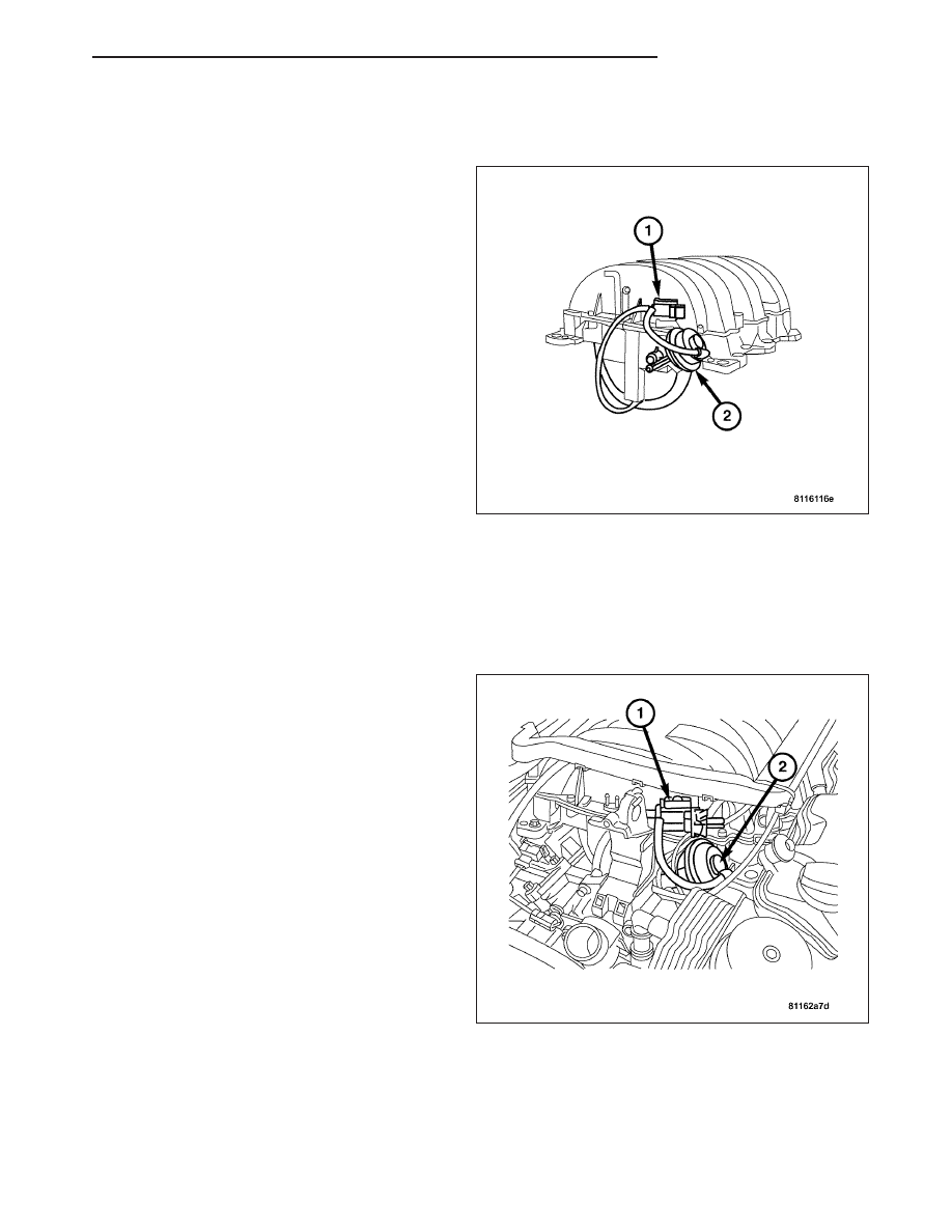
DESCRIPTION
The Manifold Tune Valve (2) opens a crossover pas-
sage internal to the intake manifold plenum. It is oper-
ated by a vacuum solenoid (1), and is controlled by
the Powertrain Control Module.
OPERATION
The Powertrain Control Module controls the Manifold Tune Valve Solenoid. The Manifold Tune Valve optimizes
acoustical tuning of the Intake System during wide open throttle operation throughout the RPM range to increase
torque.
REMOVAL
1. Disconnect the negative battery cable.
2. Remove the engine cover. (Refer to 9 - ENGINE/
AIR INTAKE SYSTEM/AIR CLEANER HOUSING -
REMOVAL).
3. Remove the air injection pump. (Refer to 25 -
EMISSIONS CONTROL/AIR INJECTION/PUMP -
REMOVAL).
4. Disconnect the manifold tune valve harness con-
nector at the manifold tune valve solenoid.
5. Disconnect the vacuum line.
6. Remove the left hand air pump switch over valve.
(Refer to 25 - EMISSIONS CONTROL/AIR INJEC-
TION/SWITCHOVER VALVE - REMOVAL).
7. Remove the nut retaining the manifold tune valve
to the valve rod.
8. Remove the manifold tune valve (2) and the sole-
noid (1) from the intake.
ZH
FUEL INJECTION
14 - 45