Chrysler Crossfire. Manual - part 690


  Index      Chrysler     Chrysler Crossfire - service repair manual 2005 year


Search            


Content   ..  688  689  690  691   ..


Chrysler Crossfire. Manual - part 690


INSTALLATION - SRT

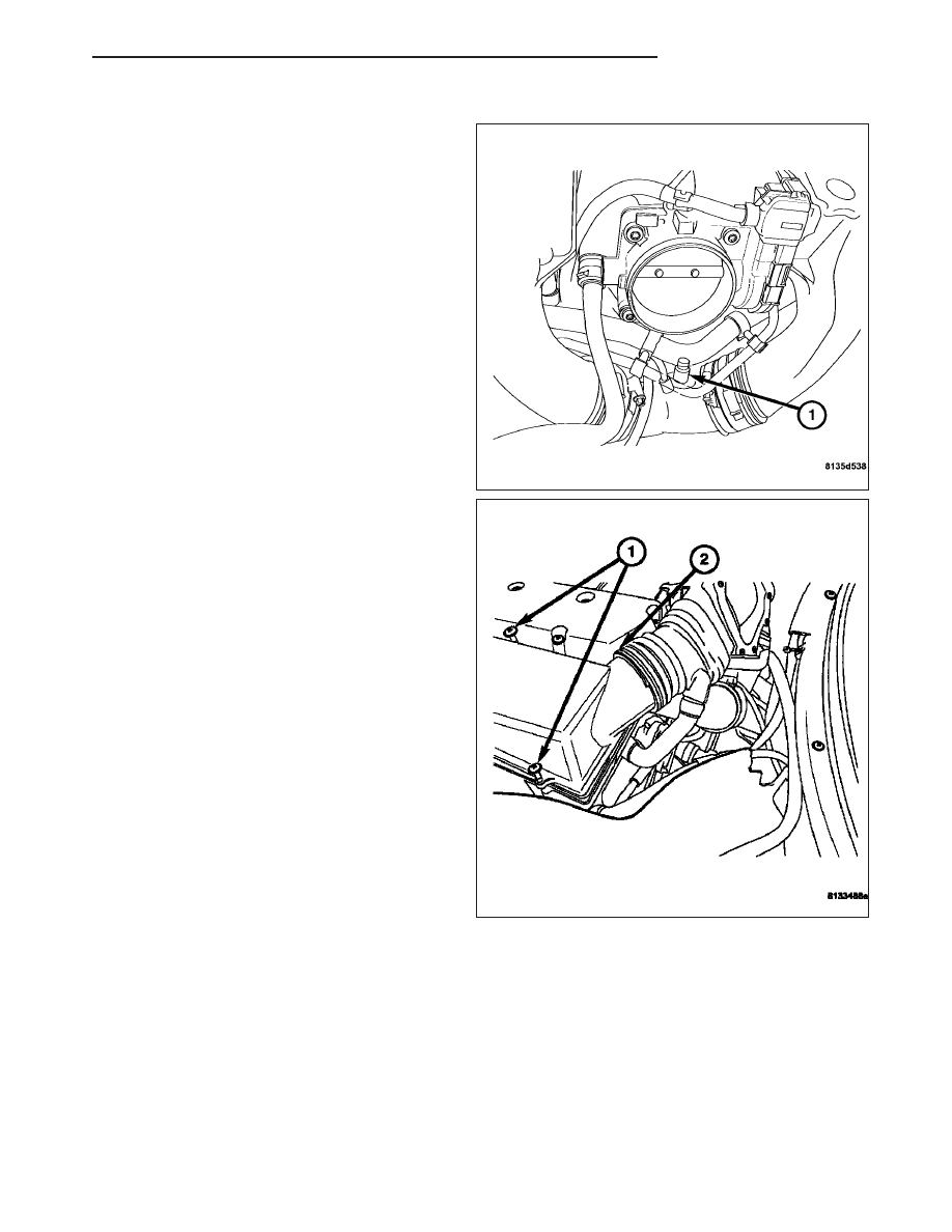
1. Install the intake air temperature sensor (1).

2. Connect the intake air temperature sensor harness

connector.

3. Install the upper air cleaner housing. (Refer to 9 -

ENGINE/AIR

INTAKE

SYSTEM/AIR

CLEANER

HOUSING - INSTALLATION).

4. Install the engine cover. Align the engine cover

retaining clips to the rubber mounts, and push
down firmly to connect engine cover to rubber
mounts.

Note: To ease the installation of the engine cover,
apply a small amount of lubricant to the engine
cover rubber mounts.

5. Connect the negative battery cable.

ZH

FUEL INJECTION

14 - 41

MANIFOLD AIR FLOW (MAF) SENSOR

DESCRIPTION

The Mass Air Flow (MAF) Sensor is located on the
rear of the engine attached to the throttle body, under
the air cleaner housing. The MAF is constructed from
plastic and also houses the Intake Air Temperature
(IAT) Sensor.

OPERATION

The Mass Air Flow (MAF) Sensor incorporates the following components:

Temperature Resistor

Sensor Resistor

Hot Film Resistor

Electronics Housing

MAF Housing

Heating Resistor

The MAF controls the temperature of the heating resistor (6) by means of a variable voltage so its temperature is
160°C (320°F) above the intake air temperature detected by the temperature resistor (1).

The temperature of the heating resistor (6) is detected by the sensor resistor (2). If a temperature change occurs as
a result of an increased or reduced air flow, the PCM adapts the voltage at the heating resistor (6) until the tem-
perature difference is again achieved.

This control voltage is used by the PCM as a measure for the metered air mass. The intake air temperature is
detected by an additional Negative Temperature Coefficient (NTC) resistor.

14 - 42

FUEL INJECTION

ZH

REMOVAL

1. Disconnect the negative battery cable.

2. Remove the engine cover. Grasp both corners of

the engine cover, and pull up firmly.

3. Disconnect the MAF/IAT harness connector (1).

4. Remove the vent hose (2).

5. Disengage the lock ring (1) that attaches the MAF

to the intake by inserting a suitable tool into the
locking ring (1) and moving the tabs on the intake
(2) away from their locked position.

6. Press the locking tab (1) on the bottom right of the

MAF down with a suitable tool unlocking it from the
intake. Press the locking tab on the upper left of
the MAF upward with a suitable tool, unlocking it
from the intake manifold.

7. Remove the MAF from the intake manifold.

8. Inspect the sealing ring and replace if necessary.

9. Inspect the sealing ring between the air inlet and

the MAF and replace if necessary.

10. Inspect the locking tabs on the MAF and replace

if necessary.

ZH

FUEL INJECTION

14 - 43

INSTALLATION

1. Install the MAF onto the intake by securely pushing

the MAF onto the throttle body.

2. Lock the lower locking tab (1) to the intake mani-

fold. Lock the upper locking tab to the intake
manifold.

3. Push the MAF so the upper locking ring (1) and

tabs (2) are inline with the tabs on the intake, then
squeeze the locking ring (1) to lock the MAF onto
the intake.

4. Install the vent hose (2) to the MAF sensor.

5. Connect the MAF/IAT harness connector (1).

6. Install the engine cover. Align the engine cover

retaining clips to the rubber mounts, and push
down firmly to connect engine cover to rubber
mounts.

Note: To ease the installation of the engine cover,
apply a small amount of lubricant to the engine
cover rubber mounts.

7. Connect the negative battery cable.

14 - 44

FUEL INJECTION

ZH


Content   ..  688  689  690  691   ..