Chrysler Crossfire. Manual - part 652


  Index      Chrysler     Chrysler Crossfire - service repair manual 2005 year


Search            


Content   ..  650  651  652  653   ..


Chrysler Crossfire. Manual - part 652


VALVE STEM SEAL

REMOVAL

Note: The tools used in these valve stem seal procedures are part of Special Tool 9106 Valve Assembly Tool
Case.

1. Remove the starter. (Refer to 8 - ELECTRICAL/STARTING/STARTER MOTOR - REMOVAL)

2. Remove the camshafts. (Refer to 9 - ENGINE/CYLINDER HEAD/CAMSHAFT(S) - REMOVAL).

3. Remove one spark plug from the cylinder to be repaired.

4. Position the cylinder to be repaired to TDC.

5. Using Special Tool 9102 Flywheel Locking Tool,

lock the flywheel by inserting the tool into the
starter opening.

6. Pressurize the combustion chamber. (Refer to 9 -

ENGINE - DIAGNOSIS AND TESTING).

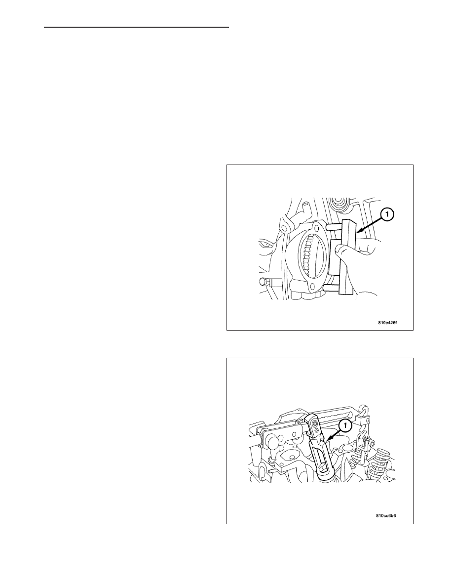
7. Install the assembly tool (1). Compress the valve

spring.

ZH

ENGINE - 3.2L SERVICE INFORMATION

9 - 753

8. With the valve spring compressed, remove the col-

lets (1).

9. Release the valve spring and remove the valve

spring retainer (2), the spring (3) and spring seat
(4).

10. Remove the valve stem seal (2) using the seal pli-

ers (1).

Note: Assemble the valves completely before
removing the air pressure from the cylinder.

11. Repeat these steps for each cylinder required.

12. Inspect all of the valve stems. Damaged valves

must be replaced.

INSTALLATION

Note: Valves with nicked or burred stems must be replaced.

Note: The tools used in these valve stem seal procedures are part of Special Tool 9106 Valve Assembly Tool
Case.

9 - 754

ENGINE - 3.2L SERVICE INFORMATION

ZH

1. Lubricate the new seal (3) with clean engine oil.

2. Install the protective sleeve (2) over the valve

stem.

3. Press the new seal over the sleeve on to the valve

stem using the seal pliers (1).

4. Remove the protective sleeve (2).

5. Install the valve spring seat (4), valve spring (3),

and the valve spring retainer (2).

ZH

ENGINE - 3.2L SERVICE INFORMATION

9 - 755

6. Compress the valve spring using the assembly tool

(1).

7. Install the valve stem collets with the valve spring

compressed.

8. Release the valve spring slowly.

9. Be sure that the collets are seated in the valve

spring retainer.

10. Remove the assembly tool.

Note: Perform this procedure on one cylinder at a
time.

11. Repeat the procedure for each valve that is to be

serviced.

12. Remove Special Tool 9102 Flywheel Locking Tool

(1).

13. Install the starter. (Refer to 8 - ELECTRICAL/

STARTING/STARTER MOTOR - INSTALLATION).

14. Install the camshafts. (Refer to 9 - ENGINE/CYL-

INDER HEAD/CAMSHAFT(S) - INSTALLATION).

INTAKE/EXHAUST VALVES AND SEALS

DESCRIPTION

Two 1.42-in. (36-mm) intake valves and a single 1.61-in. (41-mm) exhaust valve per cylinder are operated by a
double-width roller chain-driven camshaft per bank using roller rocker arms. Lightweight hydraulic adjusters in the
rocker arms at the valves take up valve clearance for quiet operation. For minimum weight and maximum rigidity the
compact rocker arms are pressure-cast aluminum. They pivot through roller bearings on rocker shafts bolted to the
heads. Using computer-aided measurement and calculation techniques, valve dynamics are equivalent to that
achieved by direct valve actuation through in-line tappets, but with far less friction.

OPERATION

The intake valve allows the air/fuel mixture to enter the combustion chamber. The exhaust valve allows the burned
air/fuel mixture to exit the combustion chamber. Also, the intake and exhaust valves seal the combustion chamber
during the compression and power strokes.

9 - 756

ENGINE - 3.2L SERVICE INFORMATION

ZH


Content   ..  650  651  652  653   ..