Chrysler Crossfire. Manual - part 629


  Index      Chrysler     Chrysler Crossfire - service repair manual 2005 year


Search            


Content   ..  627  628  629  630   ..


Chrysler Crossfire. Manual - part 629


(P2263) SUPERCHARGER CLUTCH CONTROL CIRCUIT (CONTINUED)

6.

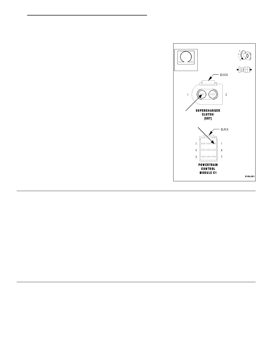
SUPERCHARGER CLUTCH CONTROL CIRCUIT OPEN

With the ignition off.

Measure the resistance of the Supercharger Clutch Control circuit from
the Supercharger Clutch harness connector to the PCM C1 harness
connector.

Is the resistance below 5.0 ohms?

Yes

>> Replace and program the Powertrain Control Module.

(Refer to 8 - ELECTRICAL/ELECTRONIC CONTROL
MODULES/POWERTRAIN

CONTROL

MODULE

-

REMOVAL).

No

>> Repair the Charcoal Canister Shutoff Valve Control circuit

for an open.

Perform POWERTRAIN VERIFICATION TEST - VER 2.

7.

INTERMITTENT WIRING AND CONNECTORS

The condition that caused this DTC to set is currently not present. Inspect the related wiring harness for a possible
intermittent condition.

Note: Check connectors — Clean/repair as necessary. Poor pin to terminal connections can set DTCs.

Note: Check for any Technical Service Bulletins that may apply.
Using the wiring diagram/schematic as a guide, inspect the wiring and connectors specific to this DTC. Wiggle the
wires while checking for shorts and open circuits.

Were there any problems found?

Yes

>> Repair as necessary.

Perform the POWERTRAIN VERIFICATION TEST - VER 2.

No

>> The condition that caused this DTC to set is currently not present. Inspect the related wiring harness for

a possible intermittent condition.

ZH

ENGINE - ELECTRICAL DIAGNOSTICS

9 - 661

(P2513) ENHANCED ACCIDENT REPORT DRIVER CIRCUIT HIGH

9 - 662

ENGINE - ELECTRICAL DIAGNOSTICS

ZH

(P2513) ENHANCED ACCIDENT REPORT DRIVER CIRCUIT HIGH (CONTINUED)

When Monitored and Set Condition

When Monitored: Ignition on.

Set Condition: The Occupant Restraint Controller (ORC) periodically sends out a signal to the Powertrain Con-
trol Module (PCM). If the PCM does not receive the signal from the ORC, the PCM will set this DTC.

POSSIBLE CAUSES

ENHANCED ACCIDENT REPORT DRIVER CIRCUIT SHORT TO VOLTAGE

ENHANCED ACCIDENT REPORT DRIVER CIRCUIT SHORT TO GROUND

ENHANCED ACCIDENT REPORT DRIVER CIRCUIT OPEN

OCCUPANT RESTRAINT CONTROLLER

POWERTRAIN CONTROL MODULE

For a complete Powertrain Control Module Circuit Diagram, (Refer to 9 - ENGINE - SCHEMATICS AND DIA-
GRAMS).

Diagnostic Test

1.

PRE-DIAGNOSTIC CHECK OUT

Note: Always perform diagnostics with a fully charged battery.

Note: Check connectors — Clean/repair as necessary. Poor pin to
terminal connections can set DTCs.

Note: Check for applicable TSBs related to the problem.
Turn the ignition on.

With the DRB III

T

, read PCM DTCs.

Using the wiring diagram/schematic as a guide, inspect the wiring and
connectors. Repair as necessary.

Perform this procedure prior to symptom diagnosis.

Continue

Go To 2

ZH

ENGINE - ELECTRICAL DIAGNOSTICS

9 - 663

(P2513) ENHANCED ACCIDENT REPORT DRIVER CIRCUIT HIGH (CONTINUED)

2.

CHECK FOR ACTIVE DTC

Note: If the PCM detects and stores a DTC, the PCM also stores
the engine/vehicle operating conditions under which the DTC was
set. Some of these conditions are displayed on the DRB III

T

at the

same time the DTC is displayed.

Note: Before erasing stored DTCs, record these conditions.
Attempting to duplicate these conditions may assist when check-
ing for an active DTC.
With the DRB III

T

, check the ORC for proper communication and

DTCs. If there are any Occupant Restraint Controller (ORC) DTCs,
repair them before continuing.

Turn the ignition on.

With the DRB III

T

, erase PCM DTCs.

Cycle the ignition switch on and off several times, pausing for at least 10 seconds at each key off and key on.

Turn the ignition on.

With the DRB III

T

, read PCM DTCs.

Did this DTC set again?

Yes

>> Go To 3

No

>> Go To 7

3.

ENHANCED ACCIDENT REPORT DRIVER CIRCUIT SHORT TO VOLTAGE

WARNING: TURN THE IGNITION OFF, DISCONNECT THE BAT-
TERY AND WAIT TWO MINUTES BEFORE PROCEEDING.

WARNING: WHEN RECONNECTING AIRBAG SYSTEM COMPO-
NENTS, THE IGNITION MUST BE TURNED OFF AND THE BAT-
TERY MUST BE DISCONNECTED.
Turn the ignition off.

Disconnect the Occupant Restraint Controller harness connector.
(Refer to 8 - ELECTRICAL/RESTRAINTS/OCCUPANT RESTRAINT
CONTROLLER - REMOVAL).

Disconnect the PCM C4 harness connectors.

Note: Check connectors — Clean/repair as necessary.
Turn the ignition on.

Measure the voltage of the Enhanced Accident Report Driver circuit.

Is the voltage below 1.0 volt?

Yes

>> Go To 4

No

>> Repair the Enhanced Accident Report Driver circuit for a short to voltage.

Perform POWERTRAIN VERIFICATION TEST - VER 2.

9 - 664

ENGINE - ELECTRICAL DIAGNOSTICS

ZH


Content   ..  627  628  629  630   ..