Chrysler Crossfire. Manual - part 553


  Index      Chrysler     Chrysler Crossfire - service repair manual 2005 year


Search            


Content   ..  551  552  553  554   ..


Chrysler Crossfire. Manual - part 553


(P0301) CYLINDER #1 MISFIRE (CONTINUED)

8.

CHECKING FUEL LEAK DOWN

WARNING: THE FUEL SYSTEM IS UNDER A CONSTANT PRESSURE (EVEN WITH THE ENGINE OFF).
BEFORE TESTING OR SERVICING ANY FUEL SYSTEM HOSE, FITTING OR LINE, THE FUEL SYSTEM PRES-
SURE MUST BE RELEASED.

Note: Before continuing visually and physically inspect the fuel delivery system for external leaks or dam-
age. Repair/replace as necessary.
Turn the ignition off.

Install a substitute fuel pressure hose between the fuel pump and fuel filter.

Start the engine and allow the fuel system to reach maximum pressure.

Turn the ignition off.

Using Special Tool #C4390, Hose Clamp Pliers, slowly clamp off the substitute fuel pressure hose between the fuel
pump and the fuel filter.

Monitor the fuel pressure gauge for a minimum of 5 minutes.

Note: The pressure should not fall below 3.0 bar (44 psi) within 5 minutes and should not fall below 2.5 bar
(36 psi) within 30 minutes.

Does the fuel pressure gauge fall below the above specification?

Yes

>> Replace the leaking component between the Fuel Pump and Injector(s).

Perform POWERTRAIN VERIFICATION TEST - VER 2.

No

>> Go To 9

Note: Remove the hose clamp pliers before continuing with test.
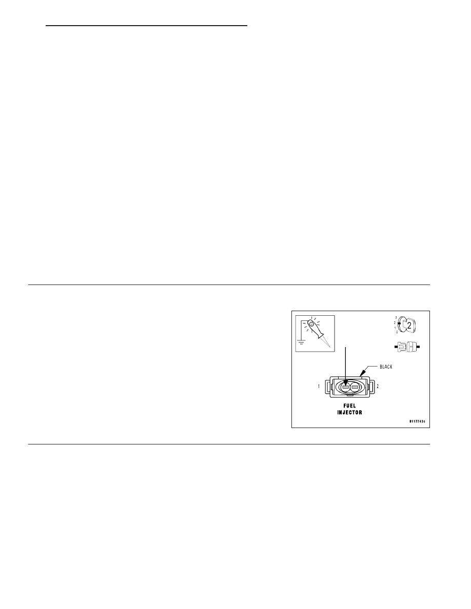
9.

ENGINE CONTROL RELAY OUTPUT CIRCUIT

Turn the ignition off.

Disconnect the Fuel Injector harness connector.

Note: Check connectors — Clean/repair as necessary.
Turn the ignition on.

Using a 12-volt test light connected to ground, probe the Engine Con-
trol Relay Output circuit at the Fuel Injector harness connector.

Does the test light illuminate brightly?

Yes

>> Go To 10

No

>> Repair the Engine Control Relay Output circuit for an

open.

Perform POWERTRAIN VERIFICATION TEST - VER 2.

ZH

ENGINE - ELECTRICAL DIAGNOSTICS

9 - 357

(P0301) CYLINDER #1 MISFIRE (CONTINUED)

10.

FUEL INJECTOR

With the ignition on.

Using a 12-volt test light connected to 12-volts, probe the Fuel Injector
Control circuit.

With the DRB III

T

, actuate the Fuel Injector Kill.

Does the test light blink?

Yes

>> Replace the Fuel Injector. (Refer to 14 - FUEL SYSTEM/

FUEL INJECTION/FUEL INJECTOR - REMOVAL).

Perform POWERTRAIN VERIFICATION TEST - VER 2.

No

>> Go To 11

11.

FUEL INJECTOR CONTROL CIRCUIT

Turn the ignition off.

Disconnect the PCM harness connector(s).

Note: Check connectors — Clean/repair as necessary.
Measure the resistance of the Fuel Injector Control circuit from the
Fuel Injector harness connector to the PCM harness connector.

Is the resistance below 5.0 ohms?

Yes

>> NOTE: Before continuing, check the PCM harness con-

nector terminals for corrosion, damage, or terminal push
out. Repair as necessary. Replace and program the Pow-
ertrain Control Module. (Refer to 8 - ELECTRICAL/ELEC-
TRONIC

CONTROL

MODULES/POWERTRAIN

CONTROL MODULE - REMOVAL).

Perform POWERTRAIN VERIFICATION TEST - VER 2.

No

>> Repair the Fuel Injector Control circuit for an open.

Perform POWERTRAIN VERIFICATION TEST - VER 2.

9 - 358

ENGINE - ELECTRICAL DIAGNOSTICS

ZH

(P0301) CYLINDER #1 MISFIRE (CONTINUED)

12.

RESTRICTED FUEL SUPPLY LINE

WARNING: THE FUEL SYSTEM IS UNDER A CONSTANT PRES-
SURE (EVEN WITH THE ENGINE OFF). BEFORE TESTING OR
SERVICING ANY FUEL SYSTEM HOSE, FITTING OR LINE, THE
FUEL SYSTEM PRESSURE MUST BE RELEASED.
Turn the ignition off.

Raise vehicle on hoist and disconnect the fuel pressure line at the fuel
pump.

Attach a fuel pressure test gauge.

Turn the ignition on.

With the DRB III

T

, actuate the Fuel Pump Relay and observe the fuel

pressure gauge.

Note: Fuel pressure specification is 3.7 to 4.2 bar (54 to 61 psi).

Is the fuel pressure within specification?

Yes

>> Repair or replace fuel supply line as necessary.

Perform POWERTRAIN VERIFICATION TEST - VER 2.

No

>> Go To 13

13.

FUEL STRAINER

WARNING: THE FUEL SYSTEM IS UNDER A CONSTANT PRESSURE (EVEN WITH THE ENGINE OFF).
BEFORE TESTING OR SERVICING ANY FUEL SYSTEM HOSE, FITTING OR LINE, THE FUEL SYSTEM PRES-
SURE MUST BE RELEASED.
Turn the ignition off.

Remove the and inspect the Fuel Strainer.

Is the Fuel Strainer plugged?

Yes

>> Replace the Fuel Strainer. (Refer to 14 - FUEL SYSTEM/FUEL DELIVERY/FUEL FILTER - REMOVAL).

Perform POWERTRAIN VERIFICATION TEST - VER 2.

No

>> NOTE: Before continuing, check the Fuel Pump Module harness connector terminals for corrosion, dam-

age, or terminal push out. Ensure the ground circuit is operating properly. Repair as necessary. Replace
the Fuel Pump. (Refer to 14 - FUEL SYSTEM/FUEL DELIVERY/FUEL PUMP - REMOVAL).

Perform POWERTRAIN VERIFICATION TEST - VER 2.

14.

FUSED IGNITION SWITCH OUTPUT CIRCUIT

Turn the ignition off.

Disconnect the Coil On Plug harness connector.

Note: Check connectors — Clean/repair as necessary.
Turn the ignition on.

Using a 12-volt test light connected to ground, probe the Fused Igni-
tion Switch Output circuit at the Coil On Plug harness connector.

Does the test light illuminate brightly?

Yes

>> Go To 15

No

>> Repair the Fused Ignition Switch Output circuit for an

open.

Perform POWERTRAIN VERIFICATION TEST - VER 2.

ZH

ENGINE - ELECTRICAL DIAGNOSTICS

9 - 359

(P0301) CYLINDER #1 MISFIRE (CONTINUED)

15.

COIL ON PLUG

Turn the ignition off.

Remove the Fuel Pump Fuse from the Relay Control Module.

Using a 12-volt test light connected to 12-volts, probe the Coil On Plug
Driver circuit.

Crank the engine for 5 second while observing the test light.

Does the test light blink/flicker?

Yes

>> Replace the Coil On Plug. (Refer to 8 - ELECTRICAL/IG-

NITION CONTROL/IGNITION COIL - REMOVAL).

Perform POWERTRAIN VERIFICATION TEST - VER 2.

No

>> Go To 16

16.

COIL ON PLUG DRIVER CIRCUIT

With the ignition off.

Disconnect the PCM harness connector.

Note: Check connectors — Clean/repair as necessary.
Check the Coil On Plug Driver circuits for a short to voltage, short to
ground, or open.

Was a problem found with the Coil On Plug Driver circuits?

Yes

>> Repair the Coil On Plug Driver circuits for the problem

found.

Perform POWERTRAIN VERIFICATION TEST - VER 2.

No

>> NOTE: Before continuing, check the PCM harness con-

nector terminals for corrosion, damage, or terminal push
out. Repair as necessary. Replace and program the Pow-
ertrain Control Module. (Refer to 8 - ELECTRICAL/ELEC-
TRONIC

CONTROL

MODULES/POWERTRAIN

CONTROL MODULE - REMOVAL).

Perform POWERTRAIN VERIFICATION TEST - VER 2.

9 - 360

ENGINE - ELECTRICAL DIAGNOSTICS

ZH


Content   ..  551  552  553  554   ..