Chrysler Crossfire. Manual - part 545


  Index      Chrysler     Chrysler Crossfire - service repair manual 2005 year


Search            


Content   ..  543  544  545  546   ..


Chrysler Crossfire. Manual - part 545


(P0223) APPS SIGNAL 2 CIRCUIT HIGH (CONTINUED)

3.

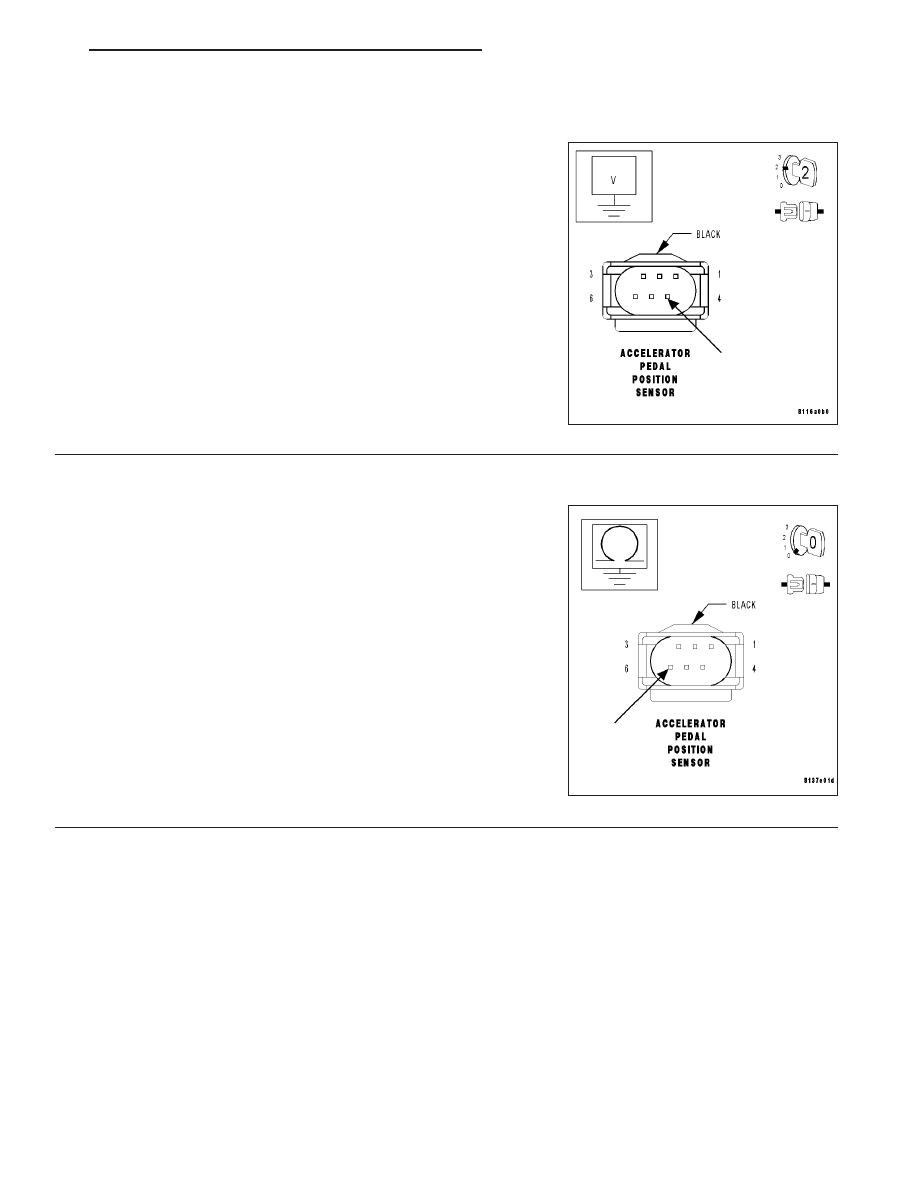
MEASURE THE APP SENSOR SIGNAL 2 VOLTAGE

Turn the ignition off.

Disconnect the APP Sensor harness connector.

Note: Check connectors — Clean/repair as necessary.
Turn the ignition on.

Measure the voltage of the APP Sensor Signal 2 circuit at the APP
Sensor harness connector.

Is the voltage below 0.05 volt?

Yes

>> Go To 4

No

>>

Go To 7

4.

MEASURE THE RESISTANCE BETWEEN GROUND AND THE SENSOR GROUND CIRCUIT

Turn the ignition off.

Measure the resistance between ground and the Sensor Ground cir-
cuit at APP Sensor harness connector cavity 6.

Is the resistance below 5.0 ohms?

Yes

>> Go To 5

No

>> Go To 6

ZH

ENGINE - ELECTRICAL DIAGNOSTICS

9 - 325

(P0223) APPS SIGNAL 2 CIRCUIT HIGH (CONTINUED)

5.

CHECK THE PCM

Turn the ignition on.

Connect a jumper wire between the APP Sensor 5-Volt Supply circuit
and the APP Sensor Signal 2 circuit at the APP Sensor harness con-
nector.

With the DRB III

T

, read the APP 2 voltage.

Note: Remove the jumper wire after this step has been com-
pleted.

Is the voltage above 4.7 volts?

Yes

>> Replace the Accelerator Pedal Position Sensor. (Refer to

14 - FUEL SYSTEM/FUEL INJECTION/ACCELERATOR
PEDAL - REMOVAL).

Perform POWERTRAIN VERIFICATION TEST - VER 2.

No

>> Go To 9

6.

SENSOR GROUND CIRCUIT OPEN

With the ignition off.

Measure the resistance of the Sensor Ground circuit from APP Sensor
harness connector cavity 3 to PCM C4 harness connector cavity 18.

Is the resistance below 5.0 ohms?

Yes

>> Go To 9

No

>> Repair the Sensor Ground circuit for an open.

Perform POWERTRAIN VERIFICATION TEST - VER 2.

9 - 326

ENGINE - ELECTRICAL DIAGNOSTICS

ZH

(P0223) APPS SIGNAL 2 CIRCUIT HIGH (CONTINUED)

7.

APP SENSOR SIGNAL 2 CIRCUIT SHORT TO VOLTAGE

Turn the ignition off.

Disconnect the PCM C4 harness connector.

Note: Check connectors — Clean/repair as necessary.
Turn the ignition on.

Measure the voltage of the APP Sensor Signal 2 circuit at the APP
Sensor harness connector.

Is the voltage below 1.0 volt?

Yes

>> Go To 8

No

>> Repair the APP Sensor Signal 2 circuit for a short to volt-

age.

Perform POWERTRAIN VERIFICATION TEST - VER 2.

8.

APP SENSOR SIGNAL 2 CIRCUIT SHORT TO APP SENSOR 5-VOLT SUPPLY CIRCUIT

Turn the ignition off.

Measure the resistance of the APP Sensor Signal 2 circuit and the
APP Sensor 5-Volt Supply circuit at the APP Sensor harness connec-
tor.

Is the resistance above 100 kohms?

Yes

>> Go To 9

No

>> Repair the APP Sensor Signal 2 circuit for a short to the

APP Sensor 5-Volt Supply circuit.

Perform POWERTRAIN VERIFICATION TEST - VER 2.

9.

PCM

Note: Before continuing, check the PCM harness connector terminals for corrosion, damage, or terminal
push out. Repair as necessary.
Using the schematics as a guide, inspect the wire harness and connectors. Pay particular attention to all Power and
Ground circuits.

If there are no possible causes remaining, view repair.

Repair

Replace and program the Powertrain Control Module. (Refer to 8 - ELECTRICAL/ELECTRONIC CON-
TROL MODULES/POWERTRAIN CONTROL MODULE - REMOVAL).

Perform POWERTRAIN VERIFICATION TEST - VER 2.

ZH

ENGINE - ELECTRICAL DIAGNOSTICS

9 - 327

(P0223) APPS SIGNAL 2 CIRCUIT HIGH (CONTINUED)

10.

CHECK THE APP SENSOR 2 SWEEP

With the ignition on.

With the DRB III

T

, monitor the APP 2 voltage.

Slowly open the throttle from the idle position to the wide open throttle
position.

Does voltage start at approximately 0.15 volt and go above 2.2
volts with a smooth transition?

Yes

>> Go To 11

No

>> Replace the Accelerator Pedal Position Sensor. (Refer to

14 - FUEL SYSTEM/FUEL INJECTION/ACCELERATOR
PEDAL - REMOVAL).

Perform POWERTRAIN VERIFICATION TEST - VER 2.

11.

INTERMITTENT WIRING AND CONNECTORS

The condition that caused this DTC to set is currently not present. Inspect the related wiring harness for a possible
intermittent condition.

Note: Check connectors — Clean/repair as necessary. Poor pin to terminal connections can set DTCs.

Note: Check for any Technical Service Bulletins that may apply.
Using the wiring diagram/schematic as a guide, inspect the wiring and connectors specific to this DTC. Wiggle the
wires while checking for shorts and open circuits.

Were there any problems found?

Yes

>> Repair as necessary.

Perform POWERTRAIN VERIFICATION TEST - VER 2.

No

>> The condition that caused this DTC to set is currently not present. Inspect the related wiring harness for

a possible intermittent condition.

9 - 328

ENGINE - ELECTRICAL DIAGNOSTICS

ZH


Content   ..  543  544  545  546   ..