Chrysler Crossfire. Manual - part 543
(P0221) ELECTRONIC THROTTLE CONTROL MODULE PROCESSOR (CONTINUED)
When Monitored and Set Condition
•
When Monitored: Ignition on with no MAP Sensor DTCs set.
•
Set Condition: TP Sensor signals in the Throttle Body do not correlate to the MAP Sensor signal.
POSSIBLE CAUSES
THROTTLE POSITION SENSOR SWEEP
THROTTLE POSITION SENSOR SIGNAL CIRCUIT SHORT TO VOLTAGE
THROTTLE POSITION SENSOR SIGNAL CIRCUIT OPEN
5-VOLT SUPPLY CIRCUIT OPEN
5-VOLT SUPPLY CIRCUIT SHORT TO GROUND
THROTTLE POSITION SENSOR GROUND CIRCUIT OPEN
TP SENSOR SIGNAL 1 CIRCUIT SHORT TO TP SENSOR SIGNAL 2 CIRCUIT
THROTTLE BODY
POWERTRAIN CONTROL MODULE
For a complete Powertrain Control Module Circuit Diagram, (Refer to 9 - ENGINE - SCHEMATICS AND DIA-
GRAMS).
Diagnostic Test
1.
CHECK FOR CURRENT DTC
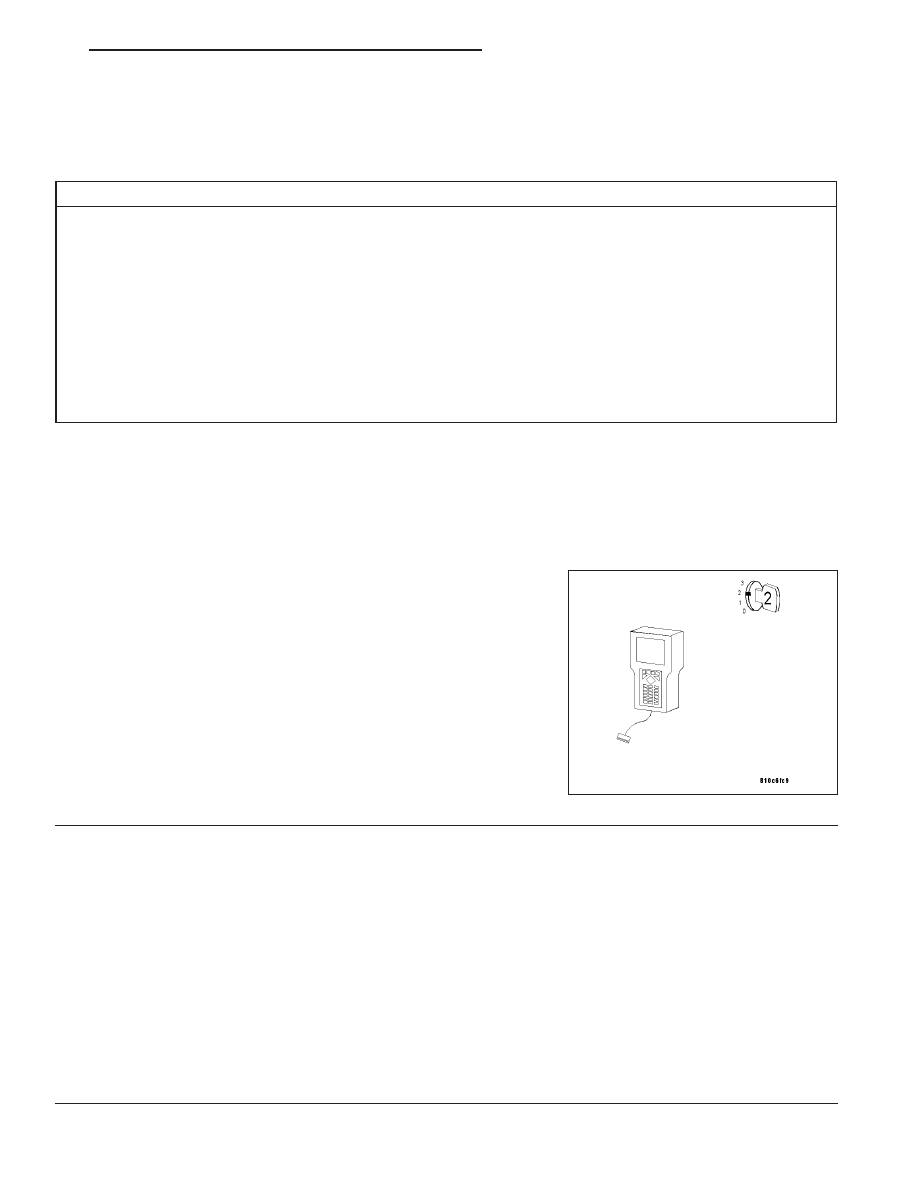
Turn the ignition on.
With the DRB III
T
, read PCM DTCs.
Is this DTC present?
Yes
>> For complete diagnosis of this DTC, refer to (P0120)
ELECTRONIC THROTTLE CONTROL MOTOR PERFOR-
MANCE.
No
>> Go To 2
2.
INTERMITTENT WIRING AND CONNECTORS
The conditions necessary to set this DTC are not present at this time.
Note: Check connectors — Clean/repair as necessary. Poor pin to terminal connections can set DTCs. Using
the wiring diagram/schematic as a guide, inspect the wiring and connectors specific to this DTC. Wiggle the
wires while checking for shorts and open circuits.
Note: Check for any Technical Service Bulletins that may apply.
Were there any problems found?
Yes
>> Repair as necessary.
Perform POWERTRAIN VERIFICATION TEST - VER 2.
No
>> The condition that caused this DTC to set is currently not present. Inspect the related wiring harness for
a possible intermittent condition.
ZH
ENGINE - ELECTRICAL DIAGNOSTICS
9 - 317