Index Chrysler Chrysler Crossfire - service repair manual 2005 year
Search
Content .. 495 496 497 498 ..
Chrysler Crossfire. Manual - part 497
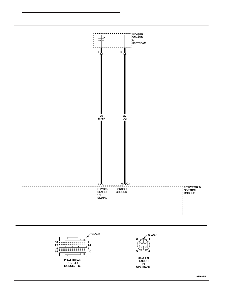
(P0133) O2 SENSOR 1/1 SHORT DELAY TIME
ZH
ENGINE - ELECTRICAL DIAGNOSTICS
9 - 133