Chrysler Crossfire. Manual - part 495
(P0131) O2 SENSOR 1/1 CIRCUIT LOW (CONTINUED)
When Monitored and Set Condition
•
When Monitored: With the engine running between 1000 and 2000 RPM, engine load between 15% to 50%,
closed loop mode, the three way catalytic converter temperature is greater than 380°C (716°F), and the O2
sensor heater must be ON for at least 220 seconds to enable the signal inactive portion of the test.
•
Set Condition: The high limit: O2 Sensor voltage is greater than 1.5 volts for approximately 5 seconds. The low
limit: O2 Sensor voltage is less than 0.15 volt for approximately 5 seconds. Signal stays at center: The O2
Sensor voltage stays between 0.4 and 0.6 volt for more than approximately 15 seconds after the O2 Sensor
heater has been ON for at least 220 seconds.
POSSIBLE CAUSES
O2 SENSOR SIGNAL CIRCUIT OPEN
O2 SENSOR SIGNAL CIRCUIT SHORT TO GROUND
O2 SENSOR SIGNAL CIRCUIT SHORT TO VOLTAGE
SENSOR GROUND CIRCUIT OPEN
ENGINE EXHAUST LEAK
O2 SENSOR
POWERTRAIN CONTROL MODULE
For a complete Powertrain Control Module Circuit Diagram, (Refer to 9 - ENGINE - SCHEMATICS AND DIA-
GRAMS).
Diagnostic Test
1.
PRE-DIAGNOSTIC CHECK OUT
Note: Always perform diagnostics with a fully charged battery.
Note: Check connectors — Clean/repair as necessary. Poor pin to
terminal connections can set DTCs.
Note: Check for applicable TSBs related to the problem.
Turn the ignition on.
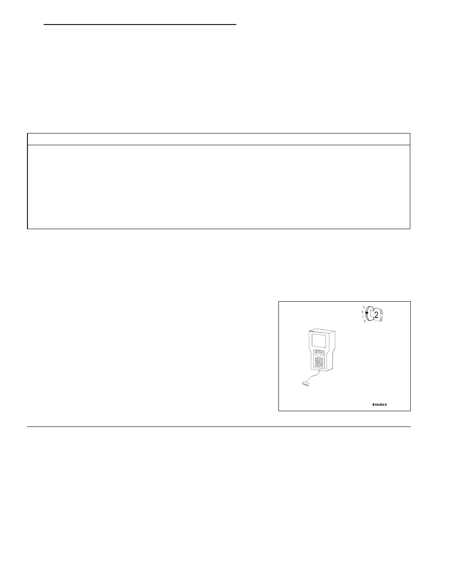
With the DRB III
T
, read PCM DTCs.
Using the wiring diagram/schematic as a guide, inspect the wiring and
connectors. Repair as necessary.
Perform this procedure prior to symptom diagnosis.
Continue
Go To 2
ZH
ENGINE - ELECTRICAL DIAGNOSTICS
9 - 125