Chrysler Crossfire. Manual - part 494


  Index      Chrysler     Chrysler Crossfire - service repair manual 2005 year


Search            


Content   ..  492  493  494  495   ..


Chrysler Crossfire. Manual - part 494


(P0128) THERMOSTAT RATIONALITY (CONTINUED)

11.

ECT SIGNAL SIGNAL CIRCUIT OPEN

Turn the ignition off.

Disconnect the PCM C3 harness connector.

Note: Check connectors — Clean/repair as necessary.
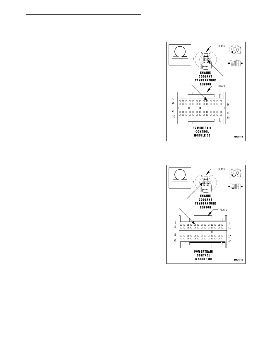
Measure the resistance of the ECT Signal circuit from the ECT Sensor
harness connector to the PCM C3 harness connector.

Is the resistance below 5.0 ohms?

Yes

>> Go To 12

No

>> Repair the ECT Signal circuit for an open.

Perform POWERTRAIN VERIFICATION TEST - VER 2.

12.

SENSOR GROUND CIRCUIT OPEN

With the ignition off.

Measure the resistance of the Sensor Ground circuit from the ECT
Sensor harness connector to the PCM C3 harness connector.

Is the resistance below 5.0 ohms?

Yes

>> Replace and program the Powertrain Control Module.

(Refer to 8 - ELECTRICAL/ELECTRONIC CONTROL
MODULES/POWERTRAIN

CONTROL

MODULE

-

REMOVAL).

Perform POWERTRAIN VERIFICATION TEST - VER 2.

No

>> Repair the Sensor Ground circuit for an open.

Perform POWERTRAIN VERIFICATION TEST - VER 2.

ZH

ENGINE - ELECTRICAL DIAGNOSTICS

9 - 121

(P0128) THERMOSTAT RATIONALITY (CONTINUED)

13.

ECT SENSOR SIGNAL CIRCUIT SHORT TO GROUND

Turn the ignition off.

Measure the resistance between ground and the ECT Sensor Signal
circuit.

Is the resistance above 100 kohms?

Yes

>> Go To 14

No

>> Repair the ECT Signal circuit for a short to ground.

Perform POWERTRAIN VERIFICATION TEST - VER 2.

14.

ECT SENSOR SIGNAL CIRCUIT SHORT TO SENSOR GROUND CIRCUIT

With the ignition off.

Measure the resistance between the Sensor Ground and the ECT
Sensor Signal circuit at the ECT Sensor harness connector.

Is the resistance above 100 kohms?

Yes

>> Replace and program the Powertrain Control Module.

(Refer to 8 - ELECTRICAL/ELECTRONIC CONTROL
MODULES/POWERTRAIN

CONTROL

MODULE

-

REMOVAL).

Perform POWERTRAIN VERIFICATION TEST - VER 2.

No

>> Repair the Sensor Ground circuit for a short to the ECT

Signal circuit.

Perform POWERTRAIN VERIFICATION TEST - VER 2.

15.

INTERMITTENT WIRING AND CONNECTORS

The condition that caused this DTC to set is currently not present. Inspect the related wiring harness for a possible
intermittent condition.

Note: Check connectors — Clean/repair as necessary. Poor pin to terminal connections can set DTCs.
Using the wiring diagram/schematic as a guide, inspect the wiring and connectors specific to this DTC. Wiggle the
wires while checking for shorts and open circuits.

Note: Check for any Technical Service Bulletins that may apply.

Were there any problems found?

Yes

>> Repair as necessary.

Perform POWERTRAIN VERIFICATION TEST - VER 2.

No

>> The condition that caused this DTC to set is currently not present. Inspect the related wiring harness for

a possible intermittent condition.

9 - 122

ENGINE - ELECTRICAL DIAGNOSTICS

ZH

(P0131) O2 SENSOR 1/1 CIRCUIT LOW

ZH

ENGINE - ELECTRICAL DIAGNOSTICS

9 - 123

(P0131) O2 SENSOR 1/1 CIRCUIT LOW (CONTINUED)

9 - 124

ENGINE - ELECTRICAL DIAGNOSTICS

ZH


Content   ..  492  493  494  495   ..