Chrysler Crossfire. Manual - part 491
(P0123) APPS SIGNAL 1 CIRCUIT HIGH (CONTINUED)
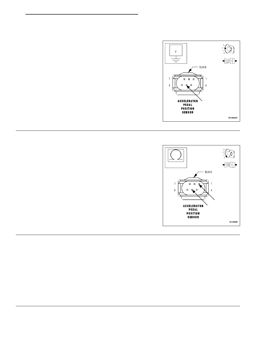
7.
APP SENSOR SIGNAL 1 CIRCUIT SHORT TO VOLTAGE
Turn the ignition off.
Disconnect the PCM C4 harness connector.
Note: Check connectors — Clean/repair as necessary.
Turn the ignition on.
Measure the voltage of the APP Sensor Signal 1 circuit at the APP
Sensor harness connector.
Is the voltage below 1.0 volt?
Yes
>> Go To 8
No
>> Repair the APP Sensor Signal 1 circuit for a short to volt-
age.
Perform POWERTRAIN VERIFICATION TEST - VER 2.
8.
APP SENSOR SIGNAL 1 CIRCUIT SHORT TO APP SENSOR 5-VOLT SUPPLY CIRCUIT
Turn the ignition off.
Measure the resistance of the APP Sensor Signal 1 circuit and the
APP Sensor 5-Volt Supply circuit at the APP Sensor harness connec-
tor.
Is the resistance above 100 kohms?
Yes
>> Go To 9
No
>> Repair the APP Sensor Signal 1 circuit for a short to the
APP Sensor 5-Volt Supply circuit.
Perform POWERTRAIN VERIFICATION TEST - VER 2.
9.
PCM
Note: Before continuing, check the PCM harness connector terminals for corrosion, damage, or terminal
push out. Repair as necessary.
Using the schematics as a guide, inspect the wire harness and connectors. Pay particular attention to all Power and
Ground circuits.
If there are no possible causes remaining, view repair.
Repair
Replace and program the Powertrain Control Module. (Refer to 8 - ELECTRICAL/ELECTRONIC CON-
TROL MODULES/POWERTRAIN CONTROL MODULE - REMOVAL).
Perform POWERTRAIN VERIFICATION TEST - VER 2.
ZH
ENGINE - ELECTRICAL DIAGNOSTICS
9 - 109