Chrysler Crossfire. Manual - part 489
(P0122) APPS SIGNAL 1 CIRCUIT LOW (CONTINUED)
3.
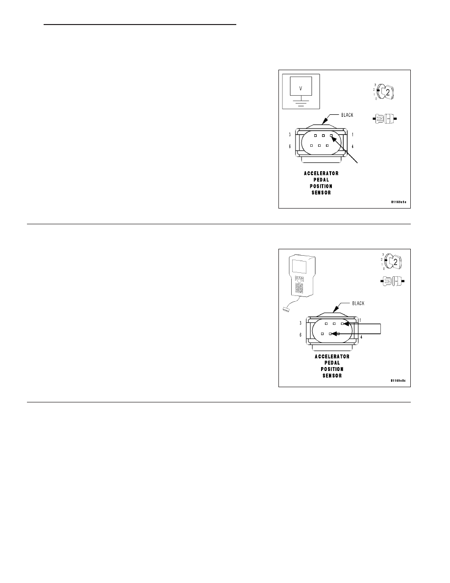
APP SENSOR 5-VOLT SUPPLY CIRCUIT
Turn the ignition off.
Disconnect the APP Sensor harness connector.
Note: Check connectors — Clean/repair as necessary.
Turn the ignition on.
Measure the voltage of the APP Sensor 5-Volt Supply circuit at the
APP Sensor harness connector.
Is the voltage between 4.7 and 5.2 volts?
Yes
>> Go To 4
No
>> Go To 8
4.
APP SENSOR
With the ignition on.
Connect a jumper wire between the APP Sensor 5-Volt Supply circuit
and the APP Sensor Signal 1 circuit in the APP Sensor harness con-
nector.
With the DRB III
T
, read the APP 1 voltage.
Note: Remove the jumper wire after this step has been com-
pleted.
Is the voltage above 4.7 volts?
Yes
>> Replace the Accelerator Pedal Position Sensor. (Refer to
14 - FUEL SYSTEM/FUEL INJECTION/ACCELERATOR
PEDAL - REMOVAL).
Perform POWERTRAIN VERIFICATION TEST - VER 2.
No
>> Go To 5
ZH
ENGINE - ELECTRICAL DIAGNOSTICS
9 - 101