Index Chrysler Chrysler Crossfire - service repair manual 2005 year
Search
Content .. 488 489 490 491 ..
Chrysler Crossfire. Manual - part 490
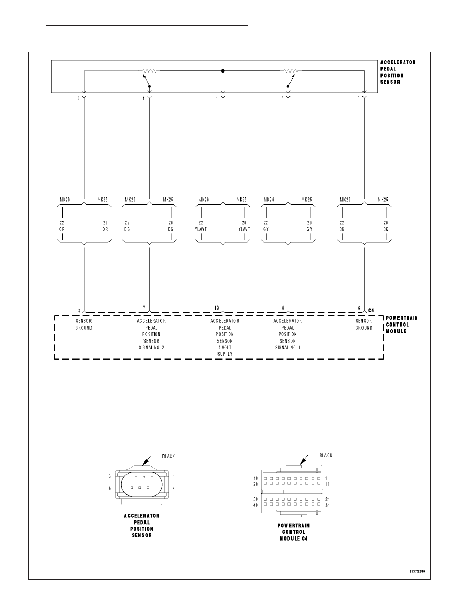
(P0123) APPS SIGNAL 1 CIRCUIT HIGH
ZH
ENGINE - ELECTRICAL DIAGNOSTICS
9 - 105