Chrysler Crossfire. Manual - part 488
(P0121) APPS 5-VOLT SUPPLY CIRCUIT (CONTINUED)
8.
MEASURE RESISTANCE BETWEEN THE TP SENSOR 5-VOLT SUPPLY CIRCUIT AND SENSOR GROUND
CIRCUITS
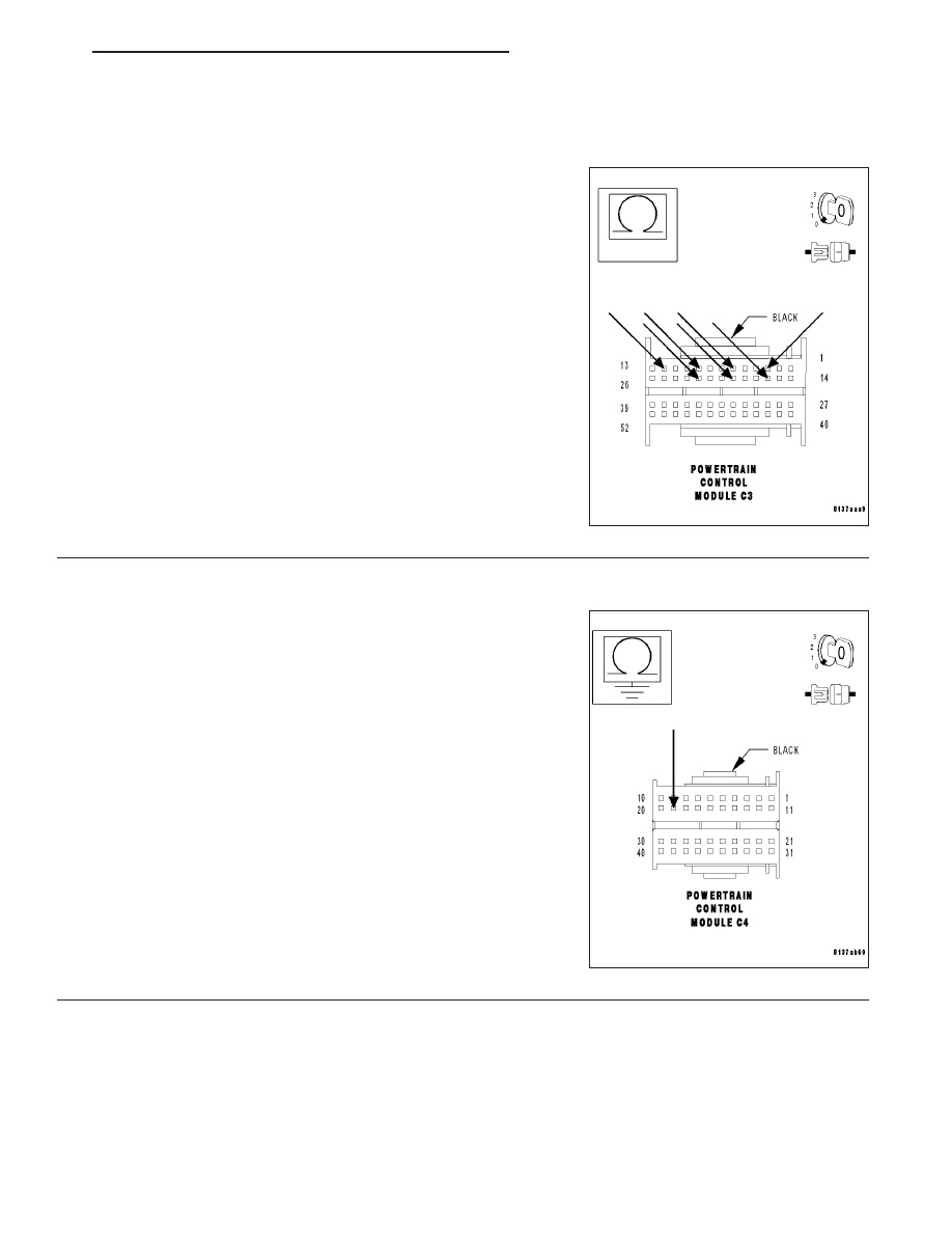
With the ignition off.
Measure the resistance between the 5-Volt Supply circuit and all Sen-
sor Ground circuits in the PCM C3 harness connector.
Is the resistance above 100 kohms for all measurements?
Yes
>> Go To 9
No
>> Repair the 5-Volt Supply circuit for a short to the Sensor
Ground circuit that measured below 100 kohms.
Perform POWERTRAIN VERIFICATION TEST - VER 2.
9.
MEASURE THE RESISTANCE BETWEEN GROUND AND THE APP SENSOR 5-VOLT SUPPLY CIRCUIT
With the ignition off.
Disconnect the PCM C4 harness connector.
Note: Check connectors — Clean/repair as necessary.
Measure the resistance between ground and the APP Sensor 5-Volt
Supply circuit at the PCM C4 harness connector.
Is the resistance above 100 kohms?
Yes
>> Go To 10
No
>> Repair the APP Sensor 5-Volt Supply circuit for a short to
ground.
Perform POWERTRAIN VERIFICATION TEST - VER 2.
ZH
ENGINE - ELECTRICAL DIAGNOSTICS
9 - 97