Chrysler Crossfire. Manual - part 299


  Index      Chrysler     Chrysler Crossfire - service repair manual 2005 year


Search            


Content   ..  297  298  299  300   ..


Chrysler Crossfire. Manual - part 299


LIFTGATE LOCK SWITCH

REMOVAL

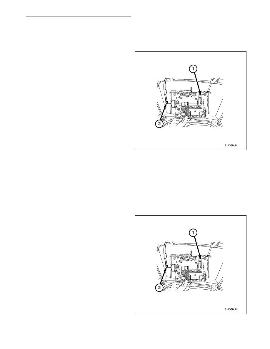
The liftgate lock switch (1) is serviced with the liftgate
latch assembly. For complete liftgate latch removal
procedures, refer to Liftgate Latch Removal in the
Body Section. (Refer to 23 - BODY/DECKLID/HATCH/
LIFTGATE/TAILGATE/LATCH - REMOVAL).

INSTALLATION

The liftgate lock switch is serviced with the liftgate latch assembly. For complete liftgate latch installation procedures,
refer to Liftgate Latch installation in the Body Section. (Refer to 23 - BODY/DECKLID/HATCH/LIFTGATE/TAILGATE/
LATCH - INSTALLATION).

LIFTGATE LOCK ACTUATOR

REMOVAL

The liftgate lock actuator (2) is serviced with the lift-
gate exterior handle assembly. For complete liftgate
exterior handle removal procedures, refer to Liftgate
Exterior Handle removal in the Body Section. (Refer to
23 - BODY/DECKLID/HATCH/LIFTGATE/TAILGATE/
EXTERIOR HANDLE - REMOVAL).

ZH

POWER LOCKS - SERVICE INFORMATION

8N - 45

INSTALLATION

The liftgate lock actuator is serviced with the liftgate exterior handle assembly. For complete liftgate exterior handle
installation procedures, refer to Liftgate Exterior Handle installation in the Body Section. (Refer to 23 - BODY/DECK-
LID/HATCH/LIFTGATE/TAILGATE/EXTERIOR HANDLE - INSTALLATION).

SENTRY KEY REMOTE ENTRY MODULE

DESCRIPTION

The Sentry Key Remote Entry Module (SKREEM) (1)
is an integral component of the Power Lock System. It
is responsible for processing operator inputs for the
Power Lock System in addition to other systems, and
is located behind the Instrument Cluster within the
Instrument Panel (2).

DIAGNOSIS AND TESTING

WARNING: REFER TO RESTRAINTS BEFORE ATTEMPTING ANY DOOR, SEAT, STEERING WHEEL, STEER-
ING COLUMN, OR INSTRUMENT PANEL COMPONENT DIAGNOSIS OR SERVICE. FAILURE TO TAKE THE
PROPER PRECAUTIONS COULD RESULT IN ACCIDENTAL AIRBAG DEPLOYMENT AND POSSIBLE PER-
SONAL INJURY. (Refer to 8 - ELECTRICAL/RESTRAINTS - WARNING).

When troubleshooting problems related to the pneumatic portion of the Power Lock System, a preliminary inspection
should be performed to determine that the supply lines, actuators, and harness connectors are free from damage.
If necessary, repairs to the pneumatic supply system must be performed before proceeding with additional Power
Lock System diagnosis. For complete power lock system diagnosis, refer to Power Locks Electrical Diagnostics in
this section.

8N - 46

POWER LOCKS - SERVICE INFORMATION

ZH

REMOVAL

REMOVAL

1. Disconnect the negative battery cable.

2. Remove the Instrument Cluster. (Refer to 8 -

ELECTRICAL/INSTRUMENT

CLUSTER

-

REMOVAL).

3. Disconnect the 2-pin CAN BUS harness connector

(1) from the SKREEM module.

4. Disconnect the 2-pin harness connector for the

sentry key antenna ring.

5. Disconnect the 18-pin harness connector (1) from

the SKREEM module.

6. Press the retaining tabs apart.

7. Remove the SKREEM module from the base plate.

REMOVAL - REMOTE KEYLESS ENTRY RELAY

1. Remove the underhood accessory fuse block lid

(1).

ZH

POWER LOCKS - SERVICE INFORMATION

8N - 47

2. Carefully release the four tabs (1) to remove the

underhood accessory fuse block cover panel (2).

3. Remove the remote keyless entry relay (1).

8N - 48

POWER LOCKS - SERVICE INFORMATION

ZH


Content   ..  297  298  299  300   ..