Chrysler Crossfire. Manual - part 273
3. Remove the headlamp bulb access plug.
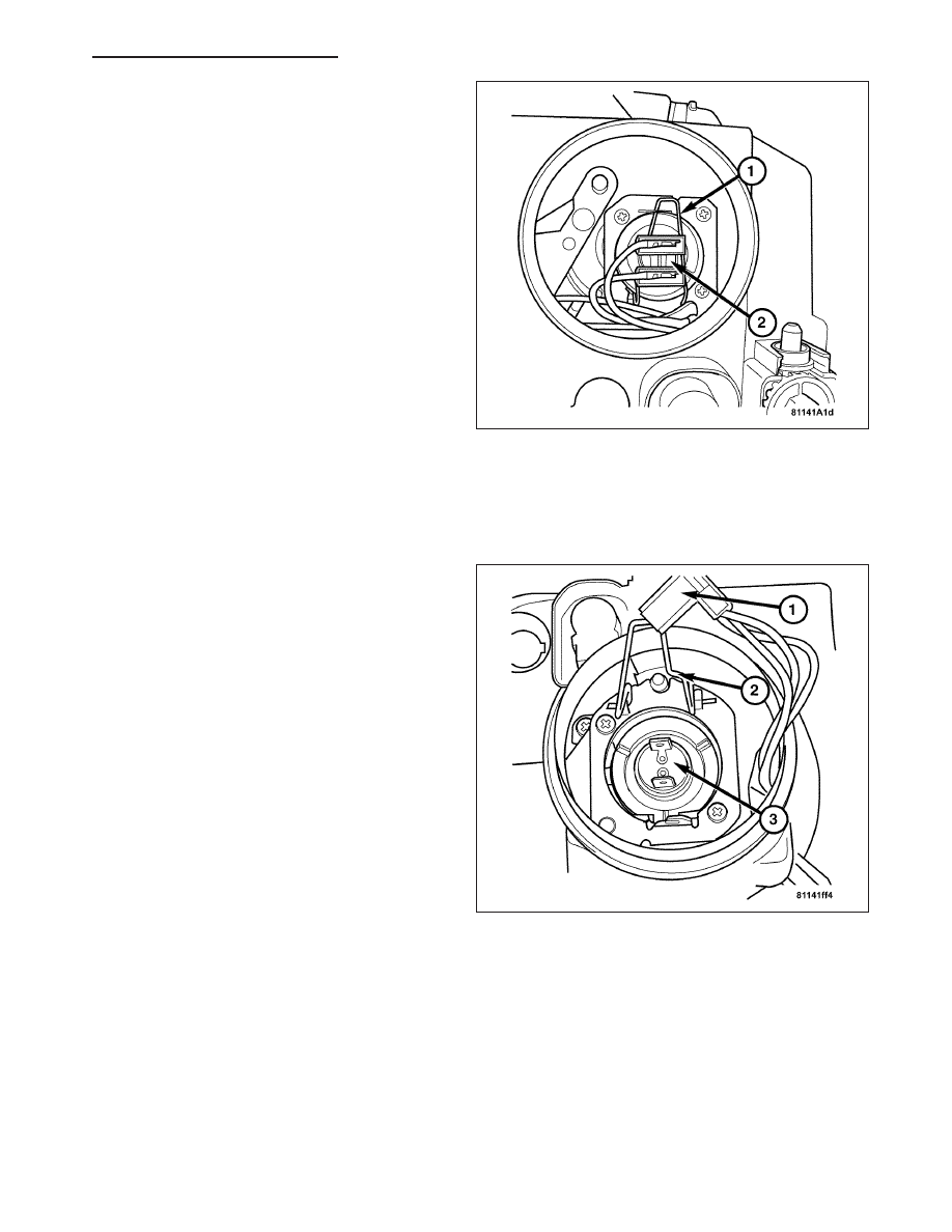
4. Disconnect the headlamp bulb harness connector
(2).
5. Disengage the bulb retaining clip (1) and remove
the bulb from the headlamp unit.
REMOVAL - HIGH BEAM BULB
1. Disconnect the negative battery cable.
2. Remove the headlamp unit. (Refer to 8 - ELECTRICAL/LAMPS/LIGHTING - EXTERIOR/HEADLAMP -
REMOVAL).
3. Remove the headlamp bulb access plug.
4. Disconnect the headlamp bulb harness connector
(1).
5. Disengage the bulb retaining clip (2) and remove
the bulb (3) from the headlamp unit.
ZH
LAMPS/LIGHTING - EXTERIOR - SERVICE INFORMATION
8L - 105