Chrysler Crossfire. Manual - part 221


  Index      Chrysler     Chrysler Crossfire - service repair manual 2005 year


Search            


Content   ..  219  220  221  222   ..


Chrysler Crossfire. Manual - part 221


FUEL LEVEL SENSOR CIRCUIT (CONTINUED)

When Monitored and Set Condition

When Monitored: With the ignition on.

Set Condition: Fuel Level Sensor circuit failure between the Fuel Level Sensor and the Instrument Cluster.

POSSIBLE CAUSES

FUEL LEVEL SENSOR CIRCUIT(S) OPEN

FUEL LEVEL SENSOR

INSTRUMENT CLUSTER

For a complete Instrument Cluster Circuit Diagram, (Refer to 8 - ELECTRICAL/INSTRUMENT CLUSTER - SCHE-
MATICS AND DIAGRAMS).

Diagnostic Test

1.

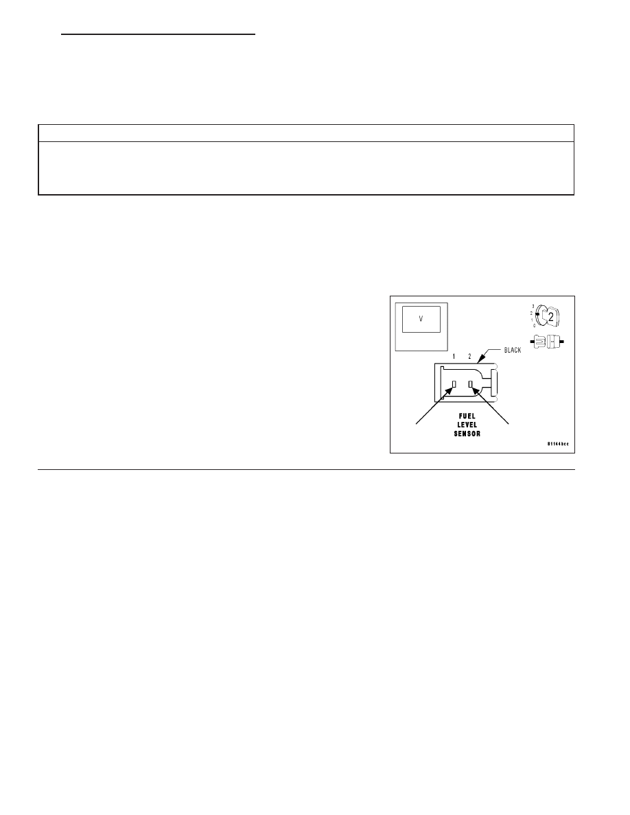
MEASURE FUEL LEVEL SENSOR CIRCUIT VOLTAGE

Turn the ignition off.

Disconnect the Fuel Level Sensor harness connector.

Note: Check connectors - Clean/repair as necessary.
Turn the ignition on.

Measure the voltage between cavity 1 and cavity 2 of the Fuel Level
Sensor harness connector.

Is the voltage approximately .7 of a volt?

Yes

>> Replace the Fuel Level Sensor. (Refer to 14 - FUEL SYS-

TEM/FUEL DELIVERY/FUEL LEVEL SENDING UNIT /
SENSOR - REMOVAL).

Perform BODY VERIFICATION TEST.

No

>> Go to 2

ZH

INSTRUMENT CLUSTER - ELECTRICAL DIAGNOSTICS

8J - 9

FUEL LEVEL SENSOR CIRCUIT (CONTINUED)

2.

MEASURE FUEL LEVEL SENSOR CIRCUIT RESISTANCE

Turn the ignition off.

Disconnect the Instrument Cluster C2 harness connector.

Note: Check connectors - Clean/repair as necessary.
Connect a jumper wire between cavity 1 and cavity 2 of the Fuel Level
Sensor harness connector.

Measure the resistance of the Fuel Level Sensor circuit from cavity D4
to cavity D5 at the Instrument Cluster C2 harness connector.

Is the resistance below 5.0 ohms?

Yes

>> Replace the Instrument Cluster. (Refer to 8 - ELECTRI-

CAL/INSTRUMENT CLUSTER - DIAGNOSIS AND TEST-
ING).

Perform BODY VERIFICATION TEST.

No

>> Repair the appropriate Fuel Level Sensor circuit for an

open.

Perform BODY VERIFICATION TEST.

8J - 10

INSTRUMENT CLUSTER - ELECTRICAL DIAGNOSTICS

ZH

AMBIENT TEMPERATURE SENSOR CIRCUIT

ZH

INSTRUMENT CLUSTER - ELECTRICAL DIAGNOSTICS

8J - 11

AMBIENT TEMPERATURE SENSOR CIRCUIT (CONTINUED)

When Monitored and Set Condition

When Monitored: With the ignition on.

Set Condition: The Instrument Cluster reports an abnormally high or low voltage that is detected on the Ambi-
ent Temperature Sensor Signal circuit.

POSSIBLE CAUSES

AMBIENT TEMPERATURE SENSOR SIGNAL CIRCUIT SHORT TO VOLTAGE

AMBIENT TEMPERATURE SENSOR OPEN

AMBIENT TEMPERATURE SENSOR SIGNAL CIRCUIT OPEN

AMBIENT TEMPERATURE SENSOR GROUND OPEN

AMBIENT TEMPERATURE SENSOR SIGNAL CIRCUIT SHORT TO GROUND

INSTRUMENT CLUSTER

For a complete Instrument Cluster Circuit Diagram, (Refer to 8 - ELECTRICAL/INSTRUMENT CLUSTER - SCHE-
MATICS AND DIAGRAMS).

Diagnostic Test

1.

READ AMBIENT TEMPERATURE SENSOR VOLTAGE WITH DRB III

T

Turn the ignition on.

With the DRB III

T

, read the Ambient Temperature Sensor voltage.

Does the DRB III

T

display AMBIENT TEMP: 5.0 VOLTS or

greater?

Yes

>> Go to 2

No

>> Go to 6

2.

MEASURE THE VOLTAGE OF THE AMBIENT TEMPERATURE SENSOR SIGNAL CIRCUIT

Turn the ignition off.

Disconnect the Ambient Temperature Sensor harness connector.

Note: Check connectors - Clean/repair as necessary.
Turn the ignition on.

Measure the voltage of the Ambient Temperature Sensor Signal circuit
at the Ambient Temperature Sensor harness connector.

Is the voltage above 5.5 volts?

Yes

>> Repair the Ambient Temperature Sensor Signal circuit for

a short to voltage.

Perform BODY VERIFICATION TEST.

No

>> Go to 3

8J - 12

INSTRUMENT CLUSTER - ELECTRICAL DIAGNOSTICS

ZH


Content   ..  219  220  221  222   ..