Chrysler Crossfire. Manual - part 157
*NO RESPONSE FROM ALL MODULES (CONTINUED)
POSSIBLE CAUSES
SENSOR GROUND CIRCUIT SHORTED TO VOLTAGE
SENSOR GROUND CIRCUIT OPEN
FUEL TANK PRESSURE SENSOR
POWERTRAIN CONTROL MODULE
For a complete Data Link Connector Circuit Diagram, (Refer to 8 - ELECTRICAL/ELECTRONIC CONTROL MOD-
ULES - SCHEMATICS AND DIAGRAMS).
Diagnostic Test
1.
CHECK PCM C4 HARNESS CONNECTOR CONNECTION
Turn the ignition off.
Disconnect the PCM C4 harness connector.
Note: Check connector — Clean/repair as necessary.
Reconnect the PCM C4 harness connector.
Turn the ignition on.
Attempt to communicate with any module with the DRB III
T
.
Does the DRB III
T
communicate with the module selected?
Yes
>> The repair is complete.
Perform POWERTRAIN VERIFICATION TEST - VER 2.
No
>> Go to 2
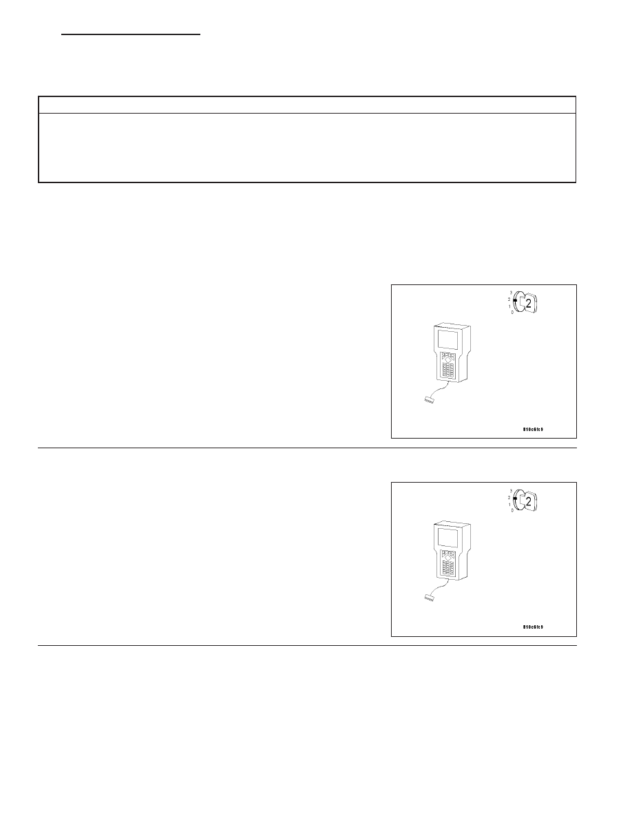
2.
DISCONNECT THE FUEL TANK PRESSURE SENSOR
Turn the ignition off.
Disconnect the Fuel Tank Pressure Sensor harness connector.
Attempt to communicate with any module with the DRB III
T
.
Does the DRB III
T
communicate with the module selected?
Yes
>> Replace the Fuel Tank Pressure Sensor. (Refer to 14 -
FUEL SYSTEM/FUEL DELIVERY/FUEL LEVEL SENDING
UNIT / SENSOR - REMOVAL).
No
>> Go to 3
ZH
ELECTRONIC CONTROL MODULES - ELECTRICAL DIAGNOSTICS
8E - 5