Chrysler Crossfire. Manual - part 158


  Index      Chrysler     Chrysler Crossfire - service repair manual 2005 year


Search            


Content   ..  156  157  158  159   ..


Chrysler Crossfire. Manual - part 158


*NO RESPONSE FROM POWERTRAIN CONTROL MODULE (CONTINUED)

POSSIBLE CAUSES

FUSED B+ CIRCUIT OPEN

FUSED ENGINE CONTROL RELAY OUTPUT CIRCUIT OPEN

PCM GROUND CIRCUITS

SCI RECEIVE CIRCUIT OPEN

SCI RECEIVE CIRCUIT SHORTED TO GROUND

SCI RECEIVE CIRCUIT SHORTED TO VOLTAGE

SCI TRANSMIT CIRCUIT OPEN

SCI TRANSMIT CIRCUIT SHORTED TO GROUND

SCI TRANSMIT CIRCUIT SHORTED TO VOLTAGE

POWERTRAIN CONTROL MODULE

For a complete Data Link Connector Circuit Diagram, (Refer to 8 - ELECTRICAL/ELECTRONIC CONTROL MOD-
ULES - SCHEMATICS AND DIAGRAMS).

Diagnostic Test

1.

CHECK COMMUNICATION WITH OTHER MODULES

Turn the ignition on.

Using the DRB III

T

, attempt to communicate with any other module.

Is the DRB III

T

able to communicate with the module selected?

Yes

>> Go to 2

No

>> Perform Symptom *No Response From All Modules.

2.

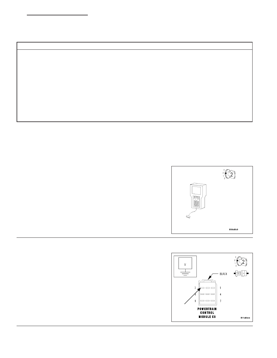
FUSED B(+) CIRCUIT OPEN

Turn the ignition off.

Disconnect the PCM C5 harness connector.

Note: Check connector — Clean/repair as necessary.
Turn the ignition on.

Measure the voltage of the Fused B(+) circuit at the PCM C5 harness
connector.

Is the voltage above 10 volts?

Yes

>> Go to 3

No

>> Repair the Fused B(+) circuit for an open.

Perform POWERTRAIN VERIFICATION TEST - VER 2.

ZH

ELECTRONIC CONTROL MODULES - ELECTRICAL DIAGNOSTICS

8E - 9

*NO RESPONSE FROM POWERTRAIN CONTROL MODULE (CONTINUED)

3.

FUSED ENGINE CONTROL RELAY OUTPUT CIRCUIT OPEN

With the ignition on.

Measure the voltage of the Fused Engine Control Relay Output circuit
at the PCM C5 harness connector.

Is the voltage above 10 volts?

Yes

>> Go to 4

No

>> Repair the Fused Engine Control Relay Output circuit for

an open.

Perform POWERTRAIN VERIFICATION TEST - VER 2.

4.

PCM GROUND CIRCUITS OPEN

Turn the ignition off.

Measure the resistance of the Ground circuits from the PCM C5 har-
ness connector to ground.

Is the resistance below 5.0 ohms on each ground circuit?

Yes

>> Go to 5

No

>> Repair the Ground circuit(s) for an open.

Perform POWERTRAIN VERIFICATION TEST - VER 2.

8E - 10

ELECTRONIC CONTROL MODULES - ELECTRICAL DIAGNOSTICS

ZH

*NO RESPONSE FROM POWERTRAIN CONTROL MODULE (CONTINUED)

5.

SCI RECEIVE CIRCUIT OPEN

With the ignition off.

Disconnect the PCM C4 harness connector.

Note: Check connector — Clean/repair as necessary.
Measure the resistance of the PCM SCI Receive circuit from the PCM
C4 harness connector to the DLC.

Is the resistance below 5.0 ohms?

Yes

>> Go to 6

No

>> Repair the PCM SCI Receive circuit for an open.

Perform POWERTRAIN VERIFICATION TEST - VER 2.

6.

SCI RECEIVE CIRCUIT SHORTED TO GROUND

With the ignition off.

Measure the resistance between ground and the PCM SCI Receive
circuit.

Is the resistance above 100 kohms?

Yes

>> Go to 7

No

>> Repair the PCM SCI Receive circuit for a short to ground.

Perform POWERTRAIN VERIFICATION TEST - VER 2.

ZH

ELECTRONIC CONTROL MODULES - ELECTRICAL DIAGNOSTICS

8E - 11

*NO RESPONSE FROM POWERTRAIN CONTROL MODULE (CONTINUED)

7.

SCI RECEIVE CIRCUIT SHORTED TO VOLTAGE

Turn the ignition on.

Measure the voltage of the PCM SCI Receive circuit at the DLC.

Is the voltage below 0.5 volt?

Yes

>> Go to 8

No

>> Repair the PCM SCI Receive circuit for a short to voltage.

Perform POWERTRAIN VERIFICATION TEST - VER 2.

8.

SCI TRANSMIT CIRCUIT OPEN

Turn the ignition off.

Measure the resistance of the PCM SCI Transmit circuit from the PCM
harness connector to the DLC.

Is the resistance below 5.0 ohms?

Yes

>> Go to 9

No

>> Repair the PCM SCI Transmit circuit for an open.

Perform POWERTRAIN VERIFICATION TEST - VER 2.

8E - 12

ELECTRONIC CONTROL MODULES - ELECTRICAL DIAGNOSTICS

ZH


Content   ..  156  157  158  159   ..