Chrysler Crossfire. Manual - part 102


  Index      Chrysler     Chrysler Crossfire - service repair manual 2005 year


Search            


Content   ..  100  101  102  103   ..


Chrysler Crossfire. Manual - part 102


BAS SOLENOID VALVE CIRCUIT (CONTINUED)

8.

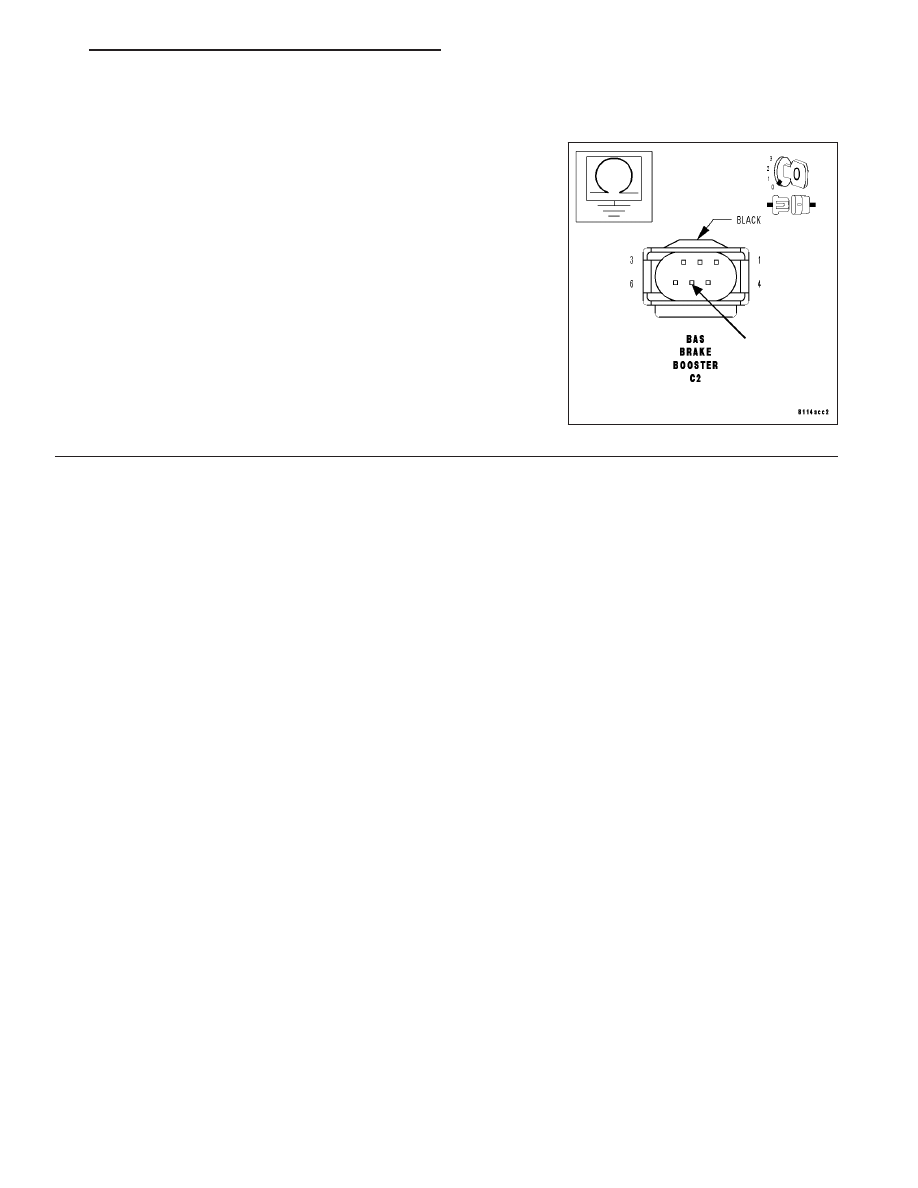
MEASURE THE RESISTANCE OF THE BAS SOLENOID VALVE CONTROL CIRCUIT

With the ignition off.

Reconnect the CAB harness connector.

Measure the resistance between ground and the BAS Solenoid Valve
Control circuit.

Is the resistance 23.5 – 24.5 kohms?

Yes

>> Replace the BAS Brake Booster. (Refer to 5 - BRAKES/

HYDRAULIC/MECHANICAL/POWER BRAKE BOOSTER -
REMOVAL).

No

>> Replace the Controller Antilock Brake. (Refer to 8 - ELEC-

TRICAL/ELECTRONIC CONTROL MODULES/CONTROL-
LER ANTILOCK BRAKE - REMOVAL).

Perform ABS VERIFICATION TEST.

ZH

BRAKES - ABS ELECTRICAL DIAGNOSTICS

5 - 241

ABS VERIFICATION TEST

ABS VERIFICATION TEST

1.

Turn the ignition off.

Disconnect all jumper wires and reconnect all previously disconnected components and connectors.

With the DRB III

T

, erase all Diagnostic Trouble Codes (DTCs) from ALL modules. Start the engine and allow it to

run for 2 minutes.

Turn the ignition off and wait 5 seconds. Turn the ignition on and using the DRB III

T

, read DTCs from ALL modules.

CAUTION: Ensure braking capability is available before road testing.

Note: For sensor signal and pump motor faults, the CAB must sense all 4 wheels at 25 km/h (15 MPH)
before the CAB will extinguish the indicator lamp.
Road test the vehicle for a minimum of 5 minutes. Perform several antilock braking stops.

Again, with the DRB III

T

, confirm that no DTCs are present and that all components are functioning properly.

If there are no DTCs present and all components are functioning properly, the repair is complete.

Are any DTCs present?

YES

>> Repair is not complete, refer to appropriate symptom.

NO

>> Repair is complete.

5 - 242

BRAKES - ABS ELECTRICAL DIAGNOSTICS

ZH

SCHEMATICS AND DIAGRAMS

ZH

BRAKES - ABS ELECTRICAL DIAGNOSTICS

5 - 243

BRAKES - ABS SERVICE INFORMATION

TABLE OF CONTENTS

page

page

BRAKES - ESP SERVICE INFORMATION

DESCRIPTION

. . . . . . . . . . . . . . . . . . . . . . . . 245

OPERATION - ELECTRONIC STABILITY

PROGRAM (ESP)

. . . . . . . . . . . . . . . . . . . . . 246

DIAGNOSIS AND TESTING - INSPECTION

AND ROAD TEST

. . . . . . . . . . . . . . . . . . . . . 248

SPECIFICATIONS - TORQUE CHART

. . . . . . . 249

FRONT WHEEL SPEED SENSOR

DESCRIPTION

. . . . . . . . . . . . . . . . . . . . . . . . 250

OPERATION

. . . . . . . . . . . . . . . . . . . . . . . . . . 250

REMOVAL

. . . . . . . . . . . . . . . . . . . . . . . . . . . . 251

INSTALLATION

. . . . . . . . . . . . . . . . . . . . . . . . 252

REAR WHEEL SPEED SENSOR

DESCRIPTION

. . . . . . . . . . . . . . . . . . . . . . . . 253

OPERATION

. . . . . . . . . . . . . . . . . . . . . . . . . . 253

REMOVAL

. . . . . . . . . . . . . . . . . . . . . . . . . . . . 254

INSTALLATION

. . . . . . . . . . . . . . . . . . . . . . . . 255

STEERING ANGLE SENSOR

DESCRIPTION

. . . . . . . . . . . . . . . . . . . . . . . . 257

OPERATION

. . . . . . . . . . . . . . . . . . . . . . . . . . 257

REMOVAL

. . . . . . . . . . . . . . . . . . . . . . . . . . . . 258

INSTALLATION

. . . . . . . . . . . . . . . . . . . . . . . . 259

LATERAL ACCELERATION SENSOR

DESCRIPTION

. . . . . . . . . . . . . . . . . . . . . . . . 260

OPERATION

. . . . . . . . . . . . . . . . . . . . . . . . . . 261

REMOVAL

. . . . . . . . . . . . . . . . . . . . . . . . . . . . 261

INSTALLATION

. . . . . . . . . . . . . . . . . . . . . . . . 261

YAW RATE SENSOR

DESCRIPTION

. . . . . . . . . . . . . . . . . . . . . . . . 262

OPERATION

. . . . . . . . . . . . . . . . . . . . . . . . . . 262

REMOVAL

. . . . . . . . . . . . . . . . . . . . . . . . . . . . 263

INSTALLATION

. . . . . . . . . . . . . . . . . . . . . . . . 263

YAW RATE/LATERAL ACCELERATION SENSOR

DESCRIPTION

. . . . . . . . . . . . . . . . . . . . . . . . 264

OPERATION

. . . . . . . . . . . . . . . . . . . . . . . . . . 264

REMOVAL

. . . . . . . . . . . . . . . . . . . . . . . . . . . . 265

INSTALLATION

. . . . . . . . . . . . . . . . . . . . . . . . 265

BRAKE PRESSURE SENSOR

DESCRIPTION

. . . . . . . . . . . . . . . . . . . . . . . . 266

OPERATION

. . . . . . . . . . . . . . . . . . . . . . . . . . 266

REMOVAL

. . . . . . . . . . . . . . . . . . . . . . . . . . . . 266

INSTALLATION

. . . . . . . . . . . . . . . . . . . . . . . . 266

TRAVEL SENSOR

DESCRIPTION

. . . . . . . . . . . . . . . . . . . . . . . . 267

OPERATION

. . . . . . . . . . . . . . . . . . . . . . . . . . 267

REMOVAL

. . . . . . . . . . . . . . . . . . . . . . . . . . . . 268

INSTALLATION

. . . . . . . . . . . . . . . . . . . . . . . . 268

SOLENOID VALVE

DESCRIPTION

. . . . . . . . . . . . . . . . . . . . . . . . 268

OPERATION

. . . . . . . . . . . . . . . . . . . . . . . . . . 268

REMOVAL

. . . . . . . . . . . . . . . . . . . . . . . . . . . . 268

INSTALLATION

. . . . . . . . . . . . . . . . . . . . . . . . 269

RELEASE SWITCH

DESCRIPTION

. . . . . . . . . . . . . . . . . . . . . . . . 269

OPERATION

. . . . . . . . . . . . . . . . . . . . . . . . . . 269

REMOVAL

. . . . . . . . . . . . . . . . . . . . . . . . . . . . 269

INSTALLATION

. . . . . . . . . . . . . . . . . . . . . . . . 269

HYDRAULIC/MECHANICAL

STANDARD PROCEDURE - BLEEDING ABS

BRAKE SYSTEM

. . . . . . . . . . . . . . . . . . . . . 270

HCU (HYDRAULIC CONTROL UNIT)

DESCRIPTION

. . . . . . . . . . . . . . . . . . . . . . . . 270

OPERATION

. . . . . . . . . . . . . . . . . . . . . . . . . . 270

REMOVAL

. . . . . . . . . . . . . . . . . . . . . . . . . . . . 271

INSTALLATION

. . . . . . . . . . . . . . . . . . . . . . . . 272

5 - 244

BRAKES - ABS SERVICE INFORMATION

ZH


Content   ..  100  101  102  103   ..