Chrysler Crossfire. Manual - part 95
BAS RELEASE SWITCH CIRCUIT (CONTINUED)
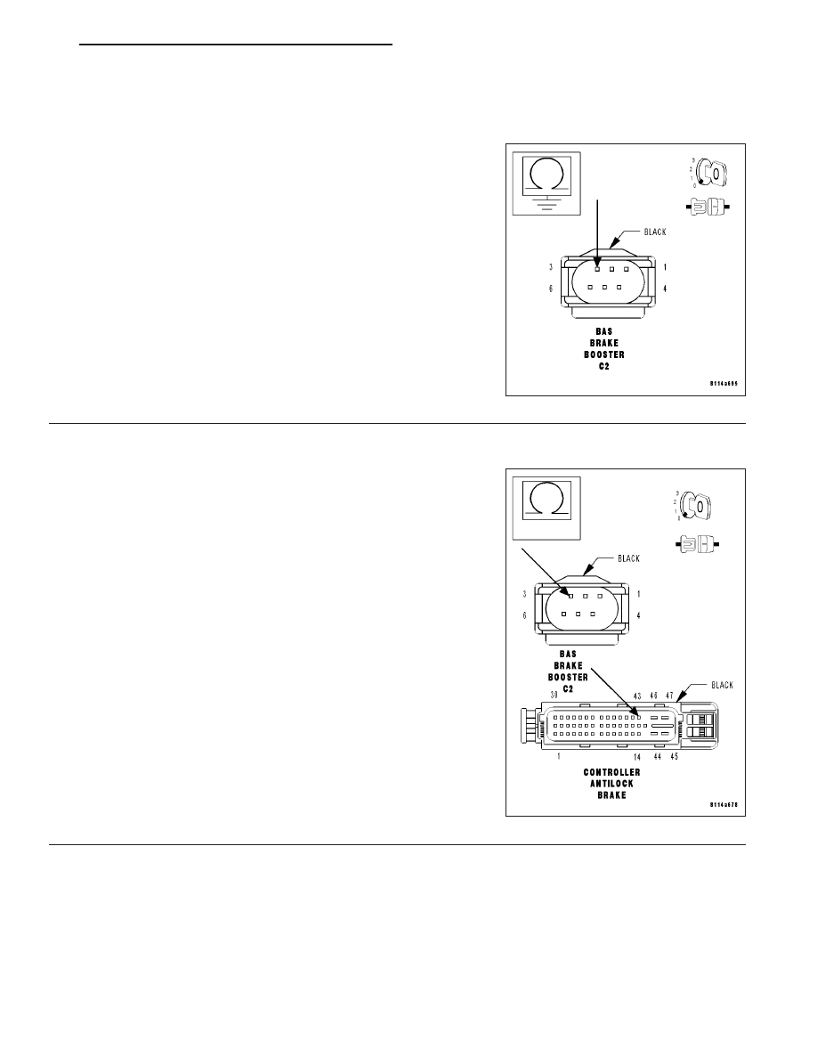
10.
MEASURE THE RESISTANCE BETWEEN GROUND AND THE BAS RELEASE SWITCH SENSOR
(APPLIED) CIRCUIT
Turn the ignition off.
Disconnect the CAB harness connector.
Note: Check connectors - Clean/repair as necessary.
Measure the resistance between ground and the BAS Release Switch
Sensor (Applied) circuit at the BAS Brake Booster C2 harness connec-
tor.
Is the resistance above 100 kohms?
Yes
>> Go to 11
No
>> Repair the BAS Release Switch Sensor (Applied) circuit
for a short to ground.
Perform ABS VERIFICATION TEST.
11.
MEASURE THE RESISTANCE OF THE BAS RELEASE SWITCH SENSOR (APPLIED) CIRCUIT
With the ignition off.
Measure the resistance of the BAS Release Switch Sensor (Applied)
circuit from the BAS Brake Booster C2 harness connector to the CAB
harness connector.
Is the resistance below 5.0 ohms?
Yes
>> Go to 12
No
>> Repair the BAS Release Switch Sensor (Applied) circuit
for an open.
Perform ABS VERIFICATION TEST.
ZH
BRAKES - ABS ELECTRICAL DIAGNOSTICS
5 - 213