Chrysler 300/300 Touring/300C, Dodge Magnum. Manual - part 390
MODULE-ANTILOCK BRAKE - MK25E
DESCRIPTION
The Antilock Brake Module (ABM) is a microproces-
sor-based device which monitors the Antilock Brake
System (ABS) during normal braking and controls it
when the vehicle is in an ABS stop. The ABM also
monitors the Electronic Stability Program (ESP) if so
equipped.
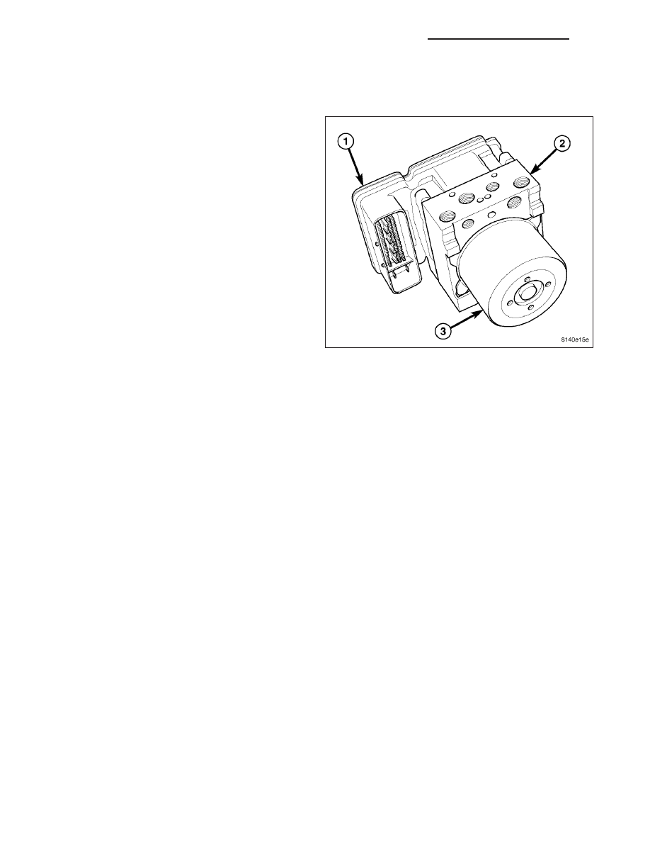
The ABM (1) is mounted to the HCU (2) as part of the
Integrated Control Unit (ICU). The ABM uses a
47-Way connector on the vehicle wiring harness. The
power source for the ABM is through the ignition
switch in the RUN or ON position. The ABM is on the
CAN-C bus.
OPERATION
The primary functions of the Antilock Brake Module (ABM) are to:
•
Monitor the Antilock Brake System (ABS) and Electronic Stability Program (ESP) for proper operation.
•
Detect wheel locking or wheel slipping tendencies by monitoring the speed of all four wheels of the vehicle.
•
Control fluid modulation to the wheel brakes while the system is in ABS or traction control mode.
•
Modulates fluid pressure to the wheel brakes to control vehicle yaw rate in ESP mode.
•
Store diagnostic information.
•
Provide communication to the scan tool while in diagnostic mode.
•
Illuminate the amber TCS/ESP indicator in the instrument cluster.
The ABM constantly monitors the ABS and ESP (if equipped) for proper operation. If the ABM detects a fault, it will
turn on the amber TCS/ESP indicator and disable the ABS or ESP if so equipped. The normal base braking system
will remain operational at that time.
The ABM continuously monitors the speed of each wheel through the signals generated by the wheel speed sensors
to determine if any wheel is beginning to lock. When a wheel locking tendency is detected, the ABM commands the
ABM solenoid coils to actuate. The coils then open and close the valves in the HCU that modulate brake fluid
pressure in some or all of the hydraulic circuits. The ABM continues to control pressure in individual hydraulic cir-
cuits until a locking tendency is no longer present.
8E - 250
ELECTRONIC CONTROL MODULES - SERVICE INFORMATION
LX