Chrysler 300/300 Touring/300C, Dodge Magnum. Manual - part 322


  Index      Chrysler     Chrysler 300/300 Touring/300C, Dodge Magnum - service repair manual


Search            


Content   ..  320  321  322  323   ..


Chrysler 300/300 Touring/300C, Dodge Magnum. Manual - part 322


2.

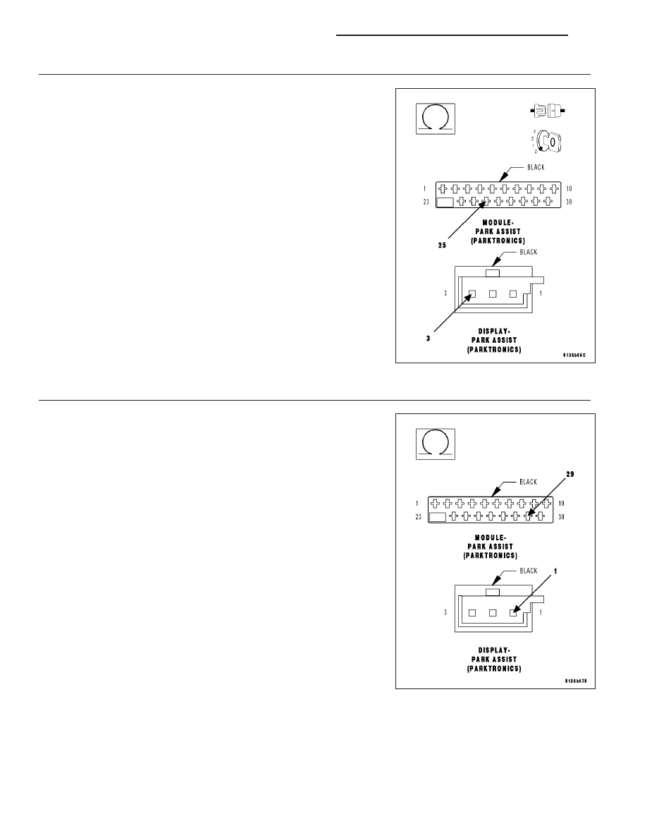
CHECK THE (D777) PARK ASSIST DISPLAY SIGNAL CIRCUIT FOR AN OPEN

Turn the ignition off.

Disconnect the Park Assist Module harness connector.

Disconnect the Park Assist Display Module harness connector.

Measure the resistance of the (D777) Park Assist Display Signal circuit
between the Park Assist Module harness connector and the Park Assist
Display harness connector.

Is the resistance below 5.0 ohms?

Yes

>> Go To 3

No

>> Repair the (D777) Park Assist Display Signal circuit for an

open.

Perform BODY VERIFICATION TEST - VER 1. (Refer to
BODY VERIFICATION TEST - VER 1).

3.

CHECK THE (X777) PARK ASSIST DISPLAY SUPPLY CIRCUIT FOR AN OPEN

Measure the resistance of the (X777) Park Assist Display Supply circuit
between the Park Assist Module harness connector and the Park Assist
Display harness connector.

Is the resistance below 5.0 ohms?

Yes

>> Go To 4

No

>> Repair the (X777) Park Assist Display Supply circuit for an

open.

Perform BODY VERIFICATION TEST - VER 1. (Refer to
BODY VERIFICATION TEST - VER 1).

8B - 54

CHIME/BUZZER - ELECTRICAL DIAGNOSTICS

LX

4.

CHECK THE (Z171) PARK ASSIST DISPLAY GROUND CIRCUIT FOR AN OPEN

Measure the resistance of the (Z171) Park Assist Display Ground circuit
between the Park Assist Module harness connector and the Park Assist
Display harness connector.

Is the resistance below 5.0 ohms?

Yes

>> Go To 5

No

>> Repair the (Z171) Park Assist Display Ground circuit for an

open.

Perform BODY VERIFICATION TEST - VER 1. (Refer to
BODY VERIFICATION TEST - VER 1).

5.

CHECK THE OPERATION OF THE PARK ASSIST DISPLAY

Replace the Park Assist Display in accordance with the service infor-
mation.

Reconnect the Park Assist Module harness connector.

Turn the ignition on.

With the scan tool, read DTCs.

Does the scan tool display U1101-LOST COMMUNICATION
WITH PTS DISPLAY?

Yes

>> Replace the Park Assist Module in accordance with the ser-

vice information.

Perform BODY VERIFICATION TEST - VER 1. (Refer to
BODY VERIFICATION TEST - VER 1).

No

>> Test Complete.

Perform BODY VERIFICATION TEST - VER 1. (Refer to BODY VERIFICATION TEST - VER 1).

U0141–LOST COMMUNICATION WITH FRONT CONTROL MODULE

For a complete wiring diagram Refer to Section 8W.

(Refer to 8 - ELECTRICAL/ELECTRONIC CONTROL MODULES - DIAGNOSIS AND TESTING) for the diagnostic
test procedure.

U0151-LOST COMMUNICATION WITH OCCUPANT RESTRAINT CONTROLLER

For a complete wiring diagram Refer to Section 8W.

LX

CHIME/BUZZER - ELECTRICAL DIAGNOSTICS

8B - 55

(Refer to 8 - ELECTRICAL/ELECTRONIC CONTROL MODULES - DIAGNOSIS AND TESTING) for the diagnostic
test procedure.

U0154-LOST COMMUNICATION WITH OCCUPANT CLASSIFICATION MODULE

For a complete wiring diagram Refer to Section 8W.

(Refer to 8 - ELECTRICAL/ELECTRONIC CONTROL MODULES - DIAGNOSIS AND TESTING) for the diagnostic
test procedure.

U0155-LOST COMMUNICATION WITH CLUSTER/CCN

For a complete wiring diagram Refer to Section 8W.

(Refer to 8 - ELECTRICAL/ELECTRONIC CONTROL MODULES - DIAGNOSIS AND TESTING) for the diagnostic
test procedure.

U0159-LOST COMMUNICATION WITH PARKING ASSIST CONTROL MODULE

For a complete wiring diagram Refer to Section 8W.

(Refer to 8 - ELECTRICAL/ELECTRONIC CONTROL MODULES - DIAGNOSIS AND TESTING) for the diagnostic
test procedure.

U0164-LOST COMMUNICATION WITH HVAC CONTROL MODULE

For a complete wiring diagram Refer to Section 8W.

(Refer to 8 - ELECTRICAL/ELECTRONIC CONTROL MODULES - DIAGNOSIS AND TESTING) for the diagnostic
test procedure.

U0167-LOST COMMUNICATION WITH INTRUSION TRANSCEIVER CONTROL
MODULE

For a complete wiring diagram Refer to Section 8W.

(Refer to 8 - ELECTRICAL/ELECTRONIC CONTROL MODULES - DIAGNOSIS AND TESTING) for the diagnostic
test procedure.

U0168-LOST COMMUNICATION WITH VEHICLE SECURITY CONTROL MODULE
(SKREEM/WCM)

For a complete wiring diagram Refer to Section 8W.

(Refer to 8 - ELECTRICAL/ELECTRONIC CONTROL MODULES - DIAGNOSIS AND TESTING) for the diagnostic
test procedure.

U0169-LOST COMMUNICATION WITH SUNROOF CONTROL MODULE

For a complete wiring diagram Refer to Section 8W.

(Refer to 8 - ELECTRICAL/ELECTRONIC CONTROL MODULES - DIAGNOSIS AND TESTING) for the diagnostic
test procedure.

U0184-LOST COMMUNICATION WITH RADIO

For a complete wiring diagram Refer to Section 8W.

8B - 56

CHIME/BUZZER - ELECTRICAL DIAGNOSTICS

LX

(Refer to 8 - ELECTRICAL/ELECTRONIC CONTROL MODULES - DIAGNOSIS AND TESTING) for the diagnostic
test procedure.

U0186-LOST COMMUNICATION WITH AUDIO AMPLIFIER

For a complete wiring diagram Refer to Section 8W.

(Refer to 8 - ELECTRICAL/ELECTRONIC CONTROL MODULES - DIAGNOSIS AND TESTING) for the diagnostic
test procedure.

U0195-LOST COMMUNICATION WITH SDARS

For a complete wiring diagram Refer to Section 8W.

(Refer to 8 - ELECTRICAL/ELECTRONIC CONTROL MODULES - DIAGNOSIS AND TESTING) for the diagnostic
test procedure.

U0196-LOST COMMUNICATION WITH VEHICLE ENTERTAINMENT CONTROL
MODULE

For a complete wiring diagram Refer to Section 8W.

(Refer to 8 - ELECTRICAL/ELECTRONIC CONTROL MODULES - DIAGNOSIS AND TESTING) for the diagnostic
test procedure.

U0197-LOST COMMUNICATION WITH HANDS FREE PHONE MODULE

For a complete wiring diagram Refer to Section 8W.

(Refer to 8 - ELECTRICAL/ELECTRONIC CONTROL MODULES - DIAGNOSIS AND TESTING) for the diagnostic
test procedure.

U0199-LOST COMMUNICATION WITH DRIVER DOOR MODULE

For a complete wiring diagram Refer to Section 8W.

(Refer to 8 - ELECTRICAL/ELECTRONIC CONTROL MODULES - DIAGNOSIS AND TESTING) for the diagnostic
test procedure.

U0200-LOST COMMUNICATION WITH PASSENGER DOOR MODULE

For a complete wiring diagram Refer to Section 8W.

(Refer to 8 - ELECTRICAL/ELECTRONIC CONTROL MODULES - DIAGNOSIS AND TESTING) for the diagnostic
test procedure.

U0208-LOST COMMUNICATION WITH HEATED SEAT CONTROL MODULE

For a complete wiring diagram Refer to Section 8W.

(Refer to 8 - ELECTRICAL/ELECTRONIC CONTROL MODULES - DIAGNOSIS AND TESTING) for the diagnostic
test procedure.

U0209-LOST COMMUNICATION WITH MEMORY SEAT CONTROL MODULE

For a complete wiring diagram Refer to Section 8W.

LX

CHIME/BUZZER - ELECTRICAL DIAGNOSTICS

8B - 57


Content   ..  320  321  322  323   ..