Content .. 1992 1993 1994 1995 ..
Chrysler 300/300 Touring/300C, Dodge Magnum. Manual - part 1994
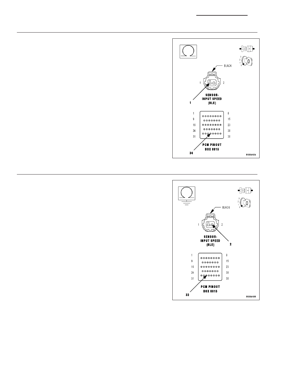
5.
(T13) SENSOR GROUND CIRCUIT OPEN
Turn the ignition off to the lock position.
Disconnect the PCM C4 harness connector.
Disconnect the Input Speed Sensor harness connector.
NOTE: Check connectors - Clean/repair as necessary.
Measure the resistance of the (T13) Sensor Ground circuit from the
from the appropriate terminal of special tool #8815 to the Input Speed
Sensor harness connector.
Is the resistance above 5.0 ohms?
Yes
>> Repair the (T13) Sensor Ground circuit for an open.
Perform 42RLE TRANSMISSION VERIFICATION TEST -
VER 1. (Refer to 21 - TRANSMISSION/TRANSAXLE/AU-
TOMATIC - 42RLE - STANDARD PROCEDURE)
No
>> Go To 6
6.
(T52) INPUT SPEED SENSOR SIGNAL CIRCUIT SHORT TO GROUND
Turn the ignition off to the lock position.
Disconnect the PCM C4 harness connector.
Disconnect the Input Speed Sensor harness connector.
NOTE: Check connectors - Clean/repair as necessary.
Measure the resistance between ground and the (T52) Input Speed
Sensor Signal circuit.
Is the resistance Below 5.0 ohms?
Yes
>> Repair the (T52) Input Speed Sensor Signal circuit for a
short to ground.
Perform 42RLE TRANSMISSION VERIFICATION TEST -
VER 1. (Refer to 21 - TRANSMISSION/TRANSAXLE/AU-
TOMATIC - 42RLE - STANDARD PROCEDURE)
No
>> Go To 7
21 - 510
AUTOMATIC TRANSMISSION 42RLE - ELECTRICAL DIAGNOSTICS
LX