Content .. 1963 1964 1965 1966 ..
Chrysler 300/300 Touring/300C, Dodge Magnum. Manual - part 1965
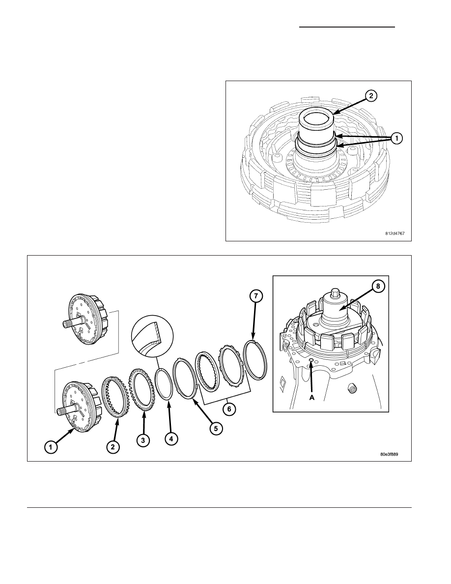
B1-HOLDING CLUTCH
DISASSEMBLY
1. Remove the teflon rings (1) from the B1 plate car-
rier hub (2).
2. Remove snap-ring (7).
3. Remove multiple-disc pack (6) and disc spring (5) from outer multiple-disc carrier. Note which clutch disc is
removed just prior to the disc spring (5) for re-assembly. If the clutch discs are re-used, this disc must be
returned to its original position on top of the disc spring.
Holding Clutch B1
1 - HOLDING CLUTCH B1 OUTER CARRIER
5 - DISC SPRING
2 - PISTON
6 - MULTIPLE DISC PACK
3 - DISC SPRING
7 - SNAP-RING
4 - SNAP-RING
8 - MULTI-USE SPRING COMPRESSOR 8900
21 - 394
AUTOMATIC TRANSMISSION NAG1 - SERVICE INFORMATION
LX