Content .. 1872 1873 1874 1875 ..
Chrysler 300/300 Touring/300C, Dodge Magnum. Manual - part 1874
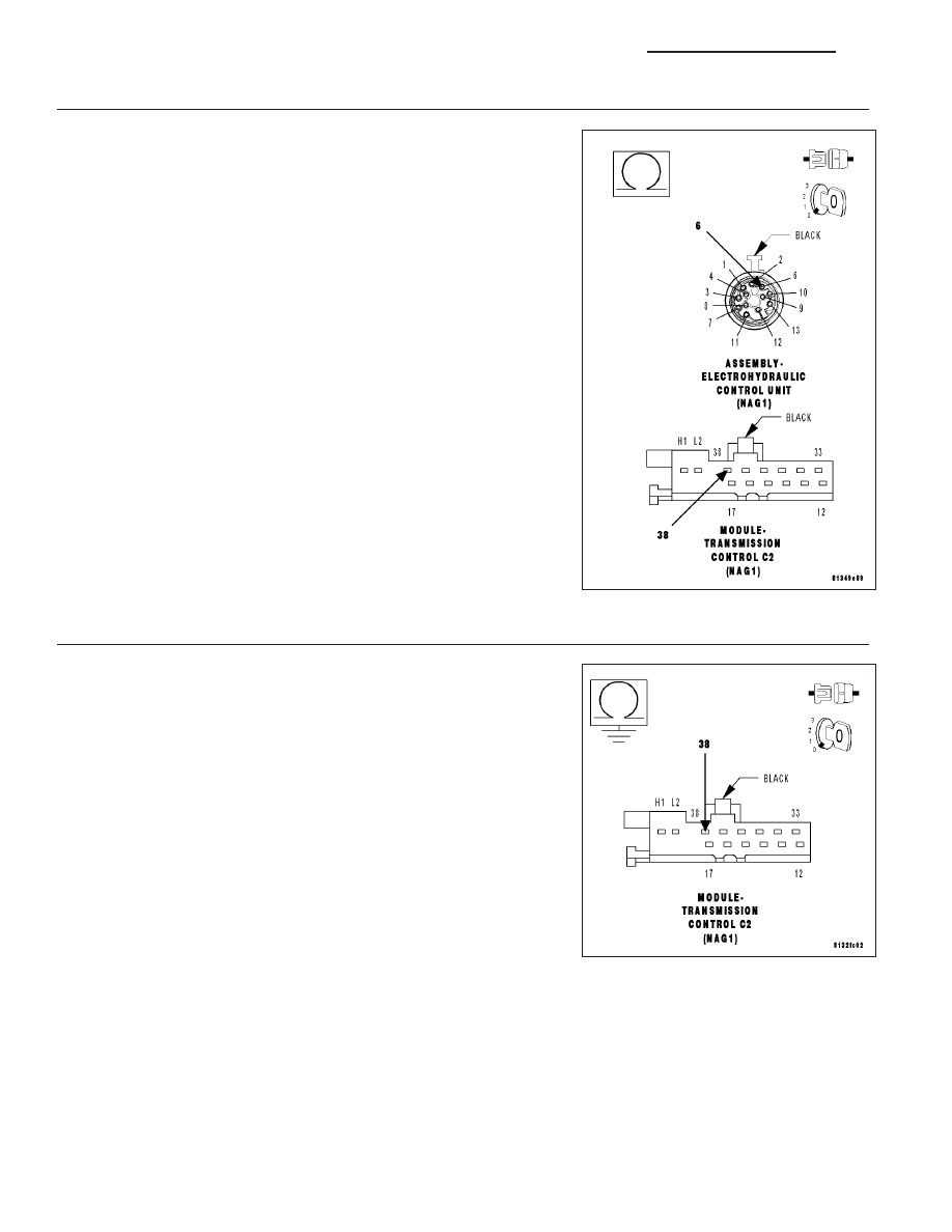
2.
(T78) SOLENOID SUPPLY VOLTAGE CIRCUIT OPEN
Turn the ignition off to the lock position.
Disconnect the TCM C1 and C2 harness connectors.
Disconnect the Electrohydraulic Control Unit Assembly harness connec-
tor.
Measure the resistance of the (T78) Solenoid Supply Voltage circuit
between the TCM C2 harness connector and the Electrohydraulic Con-
trol Unit Assembly harness connector.
Is the resistance below 5.0 ohms?
Yes
>> Repair the (T78) Solenoid Supply Voltage circuit for an
open.
Perform NAG1 TRANSMISSION VERIFICATION TEST -
VER 1. (Refer to 21 - TRANSMISSION/TRANSAXLE/AU-
TOMATIC - NAG1 - STANDARD PROCEDURE)
No
>> Go To 3
3.
(T78) SOLENOID SUPPLY VOLTAGE CIRCUIT SHORT TO GROUND
Measure the resistance between ground and the (T78) Solenoid Supply
Voltage circuit.
Is the resistance below 5.0 ohms?
Yes
>> Repair the (T78) Solenoid Supply Voltage circuit for a short
to ground.
Perform NAG1 TRANSMISSION VERIFICATION TEST -
VER 1. (Refer to 21 - TRANSMISSION/TRANSAXLE/AU-
TOMATIC - NAG1 - STANDARD PROCEDURE)
No
>> Go To 4
21 - 30
AUTOMATIC TRANSMISSION NAG1 - ELECTRICAL DIAGNOSTICS
LX