Content .. 1873 1874 1875 1876 ..
Chrysler 300/300 Touring/300C, Dodge Magnum. Manual - part 1875
3.
CHECK IF ENGINE STARTS IN PART OR NEUTRAL
Attempt to start the engine in Park or Neutral.
Does the engine start in either Park or Neutral?
Yes
>> Go To 4
No
>> Go To 5
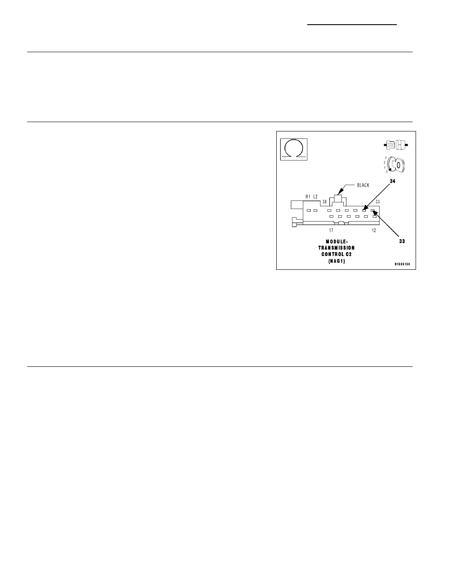
4.
TRANSMISSION TEMPERATURE SENSOR-P/N SWITCH
Turn the ignition off to the lock position.
Disconnect the TCM C2 harness connector.
Place the gear selector in Drive.
Measure the resistance of the Transmission Temperature Sensor
between the (T54) Temperature Sensor-P/N Switch Signal circuit and
the (T13) Sensor Ground circuit in the TCM C2 harness connector.
Is the resistance between 500 to 2500 ohms?
Yes
>> Using the schematics as a guide, check the Transmission
Control Module (TCM) terminals for corrosion, damage, or
terminal push out. Pay particular attention to all power and
ground circuits. If no problems are found, replace the TCM
per the Service Information. (Refer to 8 - ELECTRICAL/
ELECTRONIC
CONTROL
MODULES/TRANSMISSION
CONTROL MODULE - DESCRIPTION)
Perform NAG1 TRANSMISSION VERIFICATION TEST -
VER 1. (Refer to 21 - TRANSMISSION/TRANSAXLE/AU-
TOMATIC - NAG1 - STANDARD PROCEDURE)
No
>> Using the schematics as a guide, check the Electrohydraulic Control Unit Assembly and Transmission
Temperature Sensor-P/N Switch pins and connector terminals for corrosion, damage, or terminal push
out. If no problems are found, replace the Transmission Temperature Sensor-P/N Switch. (Refer to 21 -
TRANSMISSION/TRANSAXLE/AUTOMATIC - NAG1/ELECTROHYDRAULIC UNIT - DISASSEMBLY)
Perform NAG1 TRANSMISSION VERIFICATION TEST - VER 1. (Refer to 21 - TRANSMISSION/
TRANSAXLE/AUTOMATIC - NAG1 - STANDARD PROCEDURE)
5.
CHECK THE TRANSMISSION TEMPERATURE SENSOR-P/N SWITCH
Turn the ignition off to the lock position.
Reconnect the TCM C2 harness connector.
Disconnect the Electrohydraulic Control Unit Assembly harness connector.
NOTE: This procedure may set various DTCs to multiple modules connected to the CAN bus. Disregard and
erase any DTCs that may set after completion of this procedure.
With the Shift Lever in the Park position, attempt to start the engine.
Does the engine start?
Yes
>> Replace the Transmission Temperature Sensor-P/N Switch. (Refer to 21 - TRANSMISSION/TRANS-
AXLE/AUTOMATIC - NAG1/ELECTROHYDRAULIC UNIT - DISASSEMBLY)
Perform NAG1 TRANSMISSION VERIFICATION TEST - VER 1. (Refer to 21 - TRANSMISSION/
TRANSAXLE/AUTOMATIC - NAG1 - STANDARD PROCEDURE)
No
>> Go To 6
21 - 34
AUTOMATIC TRANSMISSION NAG1 - ELECTRICAL DIAGNOSTICS
LX