Chrysler 300/300 Touring/300C, Dodge Magnum. Manual - part 1836


  Index      Chrysler     Chrysler 300/300 Touring/300C, Dodge Magnum - service repair manual


Search            


Content   ..  1834  1835  1836  1837   ..


Chrysler 300/300 Touring/300C, Dodge Magnum. Manual - part 1836


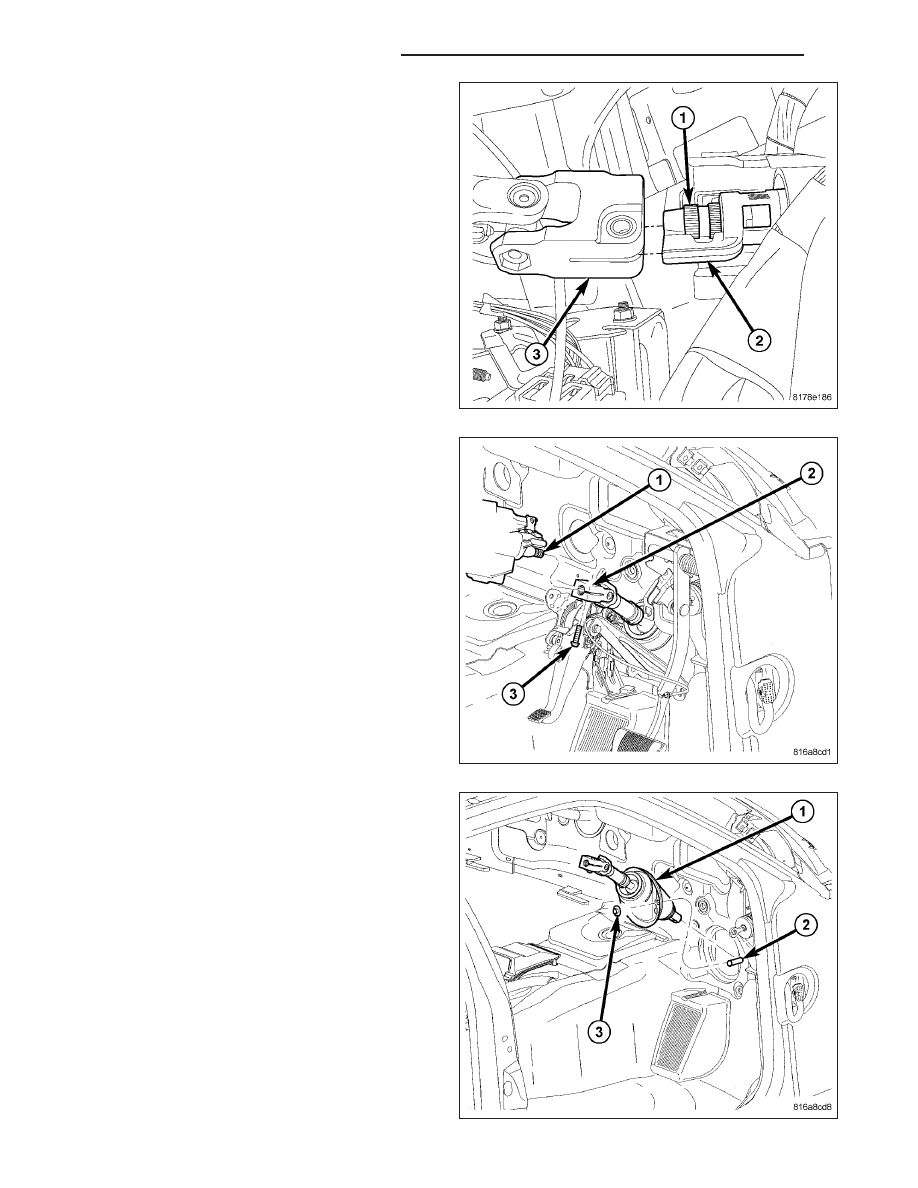
3. Align the intermediate shaft upper coupling (3) with

the steering column shaft plastic alignment fin (2),
then carefully slide the intermediate shaft onto the
column shaft (1).

4. Install a NEW steering intermediate shaft pinch bolt

(3). Tighten the pinch bolt to 31 N·m (23 ft. lbs.).

5. Install the two intermediate shaft dash seal mount-

ing nuts and tighten to 7 N·m (62 in. lbs.).

6. Raise and support the vehicle. (Refer to LUBRICA-

TION & MAINTENANCE/HOISTING - STANDARD
PROCEDURE)

19 - 162

COLUMN SERVICE INFORMATION

LX

7. Align the pin on the intermediate shaft (1) with the

nut in the lower coupling shaft (2) and slide the
intermediate shaft into the lower coupling.

8. Install a NEW steering coupling pinch bolt (3) at

the intermediate shaft. Tighten the pinch bolt to 31
N·m (23 ft. lbs.).

9. Lower the vehicle.

10. Remove the steering wheel holder.

11. Check operation of the steering column for binding or noises.

LX

COLUMN SERVICE INFORMATION

19 - 163

LEVER-ELECTRONIC TELESCOPING

REMOVAL

WARNING: Before servicing the steering column the airbag system must be disarmed. Refer to electrical
restraint system for service procedures. Failure to do so may result in accidental deployment of the airbag
and possible personal injury.

CAUTION: All fasteners must be torqued to specification to ensure proper operation of the steering column.

1. Position the front wheels straight-ahead.

2. Fully extend or pull out adjustable steering column.

3. Disconnect the negative (ground) cable from the battery.

4. Remove the airbag (3). (Refer to 8 - ELECTRICAL/

RESTRAINTS/DRIVER AIRBAG - REMOVAL).

5. Remove the steering wheel retainer bolt (2) then

slide the steering wheel (1) off the column shaft.

19 - 164

COLUMN SERVICE INFORMATION

LX

6. Remove the clockspring screws (1), (Refer to 8 -

ELECTRICAL/RESTRAINTS/CLOCKSPRING

-

REMOVAL).

7. If equipped with ESP, remove the steering angle

sensor (1) from the SCCM (2).

8. Remove the telescoping steering lever screws (4)

from the SCCM (5).

LX

COLUMN SERVICE INFORMATION

19 - 165


Content   ..  1834  1835  1836  1837   ..