Chrysler 300/300 Touring/300C, Dodge Magnum. Manual - part 1819


  Index      Chrysler     Chrysler 300/300 Touring/300C, Dodge Magnum - service repair manual


Search            


Content   ..  1817  1818  1819  1820   ..


Chrysler 300/300 Touring/300C, Dodge Magnum. Manual - part 1819


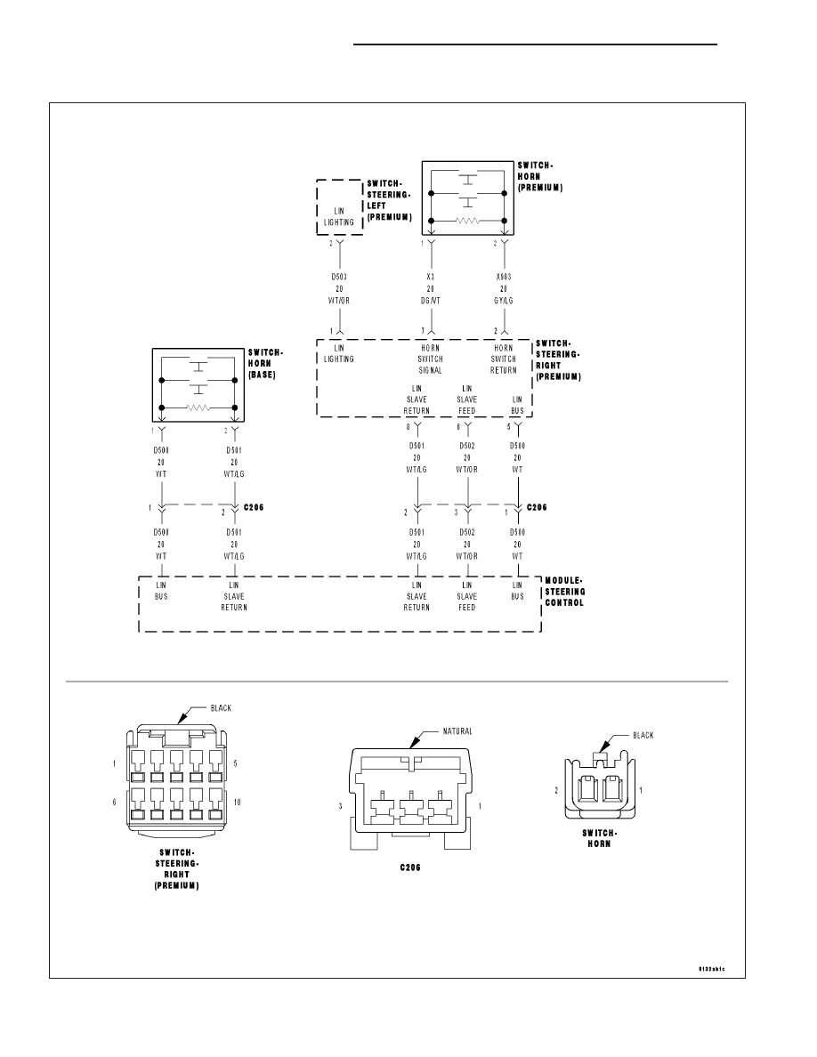
B2332–HORN SWITCH INPUT CIRCUIT/PERFORMANCE

For a complete wiring diagram Refer to Section 8W.

19 - 94

COLUMN ELECTRICAL DIAGNOSIS

LX

Theory of Operation

The Horn Switch is connected to the Right Steering Switch. The switching status is transferred to the Steering Con-
trol Module (SCM) by way of the LIN bus, a serial sub-bus. The SCM converts the data to CAN(B) and sends the
message to the corresponding module on the bus.

When Monitored:
Continuously with the ignition on.

Set Condition:
The Steering Control Module senses that the Horn Switch is in the Set position for greater than 50 seconds.

Possible Causes

INTERMITTENT HORN SWITCH INPUT CIRCUIT/PERFORMANCE DTC

(X3) HORN SWITCH SIGNAL CIRCUIT SHORT TO (X903) HORN SWITCH RETURN CIRCUIT

(X3) HORN SWITCH SIGNAL CIRCUIT SHORT TO GROUND

HORN SWITCH

RIGHT STEERING SWITCH

STEERING CONTROL MODULE (SCM)

Diagnostic Test

1.

DTC IS ACTIVE

NOTE: If P0562–BATTERY VOLTAGE LOW or P0563–BATTERY VOLTAGE HIGH is set along with this DTC,
diagnose the battery voltage DTC first.
Ignition on, engine not running.

With the Scan Tool, select View DTCs in the Steering Control Module.

Is the DTC status Active at this time?

Yes

>> Go to 2

No

>> Go to 7

2.

(X3) HORN SWITCH SIGNAL CIRCUIT SHORT TO (X903) HORN SWITCH RETURN CIRCUIT

Turn the ignition off.

Remove the Driver Airbag in accordance with the Service information.

Disconnect the Horn Switch harness connector.

Disconnect the Right Steering Switch harness connector.

NOTE: Before proceeding, thoroughly inspect the wiring harness
and connectors between the Horn Switch and the Right Steering
Switch for a short to ground or any other circuit.
Measure the resistance between the (X3) Horn Switch circuit and the
(X903) Horn Switch Return circuit.

Is the resistance below 5.0 ohms?

Yes

>> Repair the (X3) Horn Switch circuit for a short to the (X903)

Horn Switch Return circuit.

Perform the VERIFICATION TEST-VER 1.

No

>> Go to 3

LX

COLUMN ELECTRICAL DIAGNOSIS

19 - 95

3.

(X3) HORN SWITCH SIGNAL CIRCUIT SHORT TO GROUND

NOTE: Before proceeding, thoroughly inspect the wiring harness
and connectors between the Horn Switch and the Right Steering
Switch for a short to ground or to any other circuit.
Measure the resistance between the (X3) Horn Switch circuit at the har-
ness connector to the Right Switch and ground (include the metal cas-
ing at the back side of the Airbag).

Is the resistance below 5.0 ohms?

Yes

>> Repair the (X3) Horn Switch circuit for a short to ground.

No

>> Go to 4

4.

HORN SWITCH

Measure the resistance between the (X3) Horn Switch circuit and the
(X903) Horn Switch Return circuit at the harness connector to the horn
switch.

Is the resistance below 5.0 ohms?

Yes

>> Replace the Horn Switch in accordance with the Service

Information.

No

>> Go to 5

5.

RIGHT STEERING SWITCH

Turn the ignition off.

Replace the Right Steering Switch in accordance with the Service Information.

Turn the ignition on.

NOTE: The C206 (LIN bus) connector must be connected for this test.
Press and release the Horn Switch several times.

With the Scan Tool, Clear Stored DTCs in the Steering Control Module.

With the Scan Tool, select Data Display and view the Horn switch data.

While monitoring the Horn switch data, press and release the Horn Switch several times.

Does the Horn switch data change from Set to Not Set when the switch is pressed and released?

Yes

>> Test Complete.

No

>> Go to 6

19 - 96

COLUMN ELECTRICAL DIAGNOSIS

LX

6.

STEERING CONTROL MODULE (SCM)

View repair.

Repair

Replace the Steering Control Module (SCM) in accordance with the Service Information.

7.

INTERMITTENT HORN SWITCH INPUT CIRCUIT/PERFORMANCE DTC

The conditions necessary to set this DTC are not present at this time.

Using the wiring diagram/schematic as a guide, inspect the wiring and connectors.

While monitoring the scan tool data relative to this circuit, wiggle test the wiring and connectors.

Look for the data to change or for the DTC to reset during the wiggle test.

Were any problems found?

Yes

>> Repair as necessary.

No

>> Test complete.

LX

COLUMN ELECTRICAL DIAGNOSIS

19 - 97


Content   ..  1817  1818  1819  1820   ..