Chrysler 300/300 Touring/300C, Dodge Magnum. Manual - part 1817


  Index      Chrysler     Chrysler 300/300 Touring/300C, Dodge Magnum - service repair manual


Search            


Content   ..  1815  1816  1817  1818   ..


Chrysler 300/300 Touring/300C, Dodge Magnum. Manual - part 1817


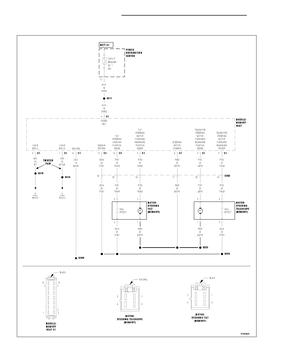
B1D97–STEERING COLUMN TILT MOTOR CONTROL CIRCUIT PERFORMANCE

For a complete wiring diagram Refer to Section 8W.

19 - 86

COLUMN ELECTRICAL DIAGNOSIS

LX

Theory of Operation

This DTC will set if movement in the Tilt Motor is requested and no motor movement is detected and only if failure
counters are matured for both motor directions (up/down). If the motor becomes energized and there are no hall
pulses recognized after motor activation, the MSM will de-energize the motor after 2 seconds.

When Monitored:
When the motor is activated in either direction, until de-energized by the MSM.

Set Condition:
No movement is detected in an activated motor for more than 2000 ms.

Possible Causes

INTERMITTENT STEERING COLUMN TILT MOTOR CONTROL CIRCUIT PERFORMANCE DTC

(P153) TILT STEERING UP/DOWN DRIVER CIRCUIT OPEN

(P153) TILT STEERING UP/DOWN DRIVER CIRCUIT SHORT TO GROUND

(P153) TILT STEERING UP/DOWN DRIVER CIRCUIT SHORT TO VOLTAGE

(P953) STEERING MOTOR COMMON CIRCUIT OPEN

(P953) STEERING MOTOR COMMON CIRCUIT SHORT TO GROUND

(P953) STEERING MOTOR COMMON CIRCUIT SHORT TO VOLTAGE

STEERING COLUMN TELESCOPE MOTOR

MEMORY SEAT MODULE (MSM)

Diagnostic Test

1.

DTC IS ACTIVE

Ignition on, engine not running.

NOTE: If a DTC is set for B1D8D and/or B1D8E, perform the diagnostic procedure(s) before continuing.
With the Scan Tool, select Clear Stored DTCs in the Memory Seat Module.

Move the Steering Column Tilt Switch to the Forward and Rearward positions several times, holding the switch in
position for at least 2 seconds each time.

With the Scan Tool, select View DTCs in the Memory Seat Module.

Does the DTC reset and/or remain active?

Yes

>> Go to 2

No

>> Go to 14

2.

(P153) TILT STEERING MOTOR UP/DOWN DRIVER CIRCUIT — TEST TO GROUND

Turn the ignition off.

Disconnect the Steering Tilt Motor harness connector.

Turn the ignition on.

Using a 12–volt test light connected to 12–volts, check the (P153) Tilt
Steering Motor Up/Down Driver circuit.

Monitor the test light with the Steering Column Tilt Switch in the Up
position, the Down position and with the switch at rest.

The test light should be illuminated and bright only when the switch is
in the Down position.

Does the test light illuminate as described?

Yes

>> Go to 3

No

>> Go to 6

LX

COLUMN ELECTRICAL DIAGNOSIS

19 - 87

3.

(P953) TILT STEERING MOTOR COMMON CIRCUIT — TEST TO GROUND

Using a 12–volt test light connected to 12–volts, check the (P953) Tilt
Steering Motor Common circuit.

Monitor the test light with the Steering Column Tilt Switch in the Up
position, the Down position and with the switch at rest.

The test light should be illuminated and bright when the switch is in the
Up position and when the switch is at rest.

Does the test light illuminate as described?

Yes

>> Go to 4

No

>> Go to 9

4.

(P153) TILT STEERING MOTOR UP/DOWN DRIVER CIRCUIT- TEST TO VOLTAGE

Using a 12–volt test light connected to ground, check the (P153) Tilt
Steering Motor Up/Down Driver circuit.

Monitor the test light with the Steering Column Tilt Switch in the Up
position, the Down position and with the switch at rest.

The test light should be illuminated and bright only when the switch is
in the Up position.

Does the test light illuminate as described?

Yes

>> Go to 5

No

>> Go to 6

5.

(P953) TILT STEERING MOTOR COMMON CIRCUIT — TEST TO VOLTAGE

Using a 12–volt test light connected to ground, check the (P953) Tilt
Steering Motor Common circuit.

Monitor the test light with the Steering Column Tilt Switch in the Up
position, the Down position and with the switch at rest.

The test light should be illuminated and bright only when the switch is
in the Down position.

Does the test light illuminate as described?

Yes

>> Go to 12

No

>> Go to 9

19 - 88

COLUMN ELECTRICAL DIAGNOSIS

LX

6.

(P153) TILT STEERING MOTOR UP/DOWN DRIVER CIRCUIT SHORT TO GROUND

Turn the ignition off.

Disconnect the Memory Seat Module (MSM) C1 connector.

Turn the ignition on.

Using a 12–volt test light connected to 12–volts, check the (P153) Tilt
Steering Motor Up/Down Driver circuit.

Does the test light illuminate?

Yes

>> Repair the (P153) Tilt Steering Motor Up/Down Driver cir-

cuit for a short to ground.

No

>> Go to 7

7.

(P153) TILT STEERING MOTOR UP/DOWN DRIVER CIRCUIT OPEN

Turn the ignition off.

Measure the resistance of the (P153) Tilt Steering Motor Up/Down
Driver circuit.

Is the resistance above 5.0 ohms?

Yes

>> Repair the (P153) Tilt Steering Motor Up/Down Driver cir-

cuit for an open.

No

>> Go to 8

LX

COLUMN ELECTRICAL DIAGNOSIS

19 - 89


Content   ..  1815  1816  1817  1818   ..