Chrysler 300/300 Touring/300C, Dodge Magnum. Manual - part 1820


  Index      Chrysler     Chrysler 300/300 Touring/300C, Dodge Magnum - service repair manual


Search            


Content   ..  1818  1819  1820  1821   ..


Chrysler 300/300 Touring/300C, Dodge Magnum. Manual - part 1820


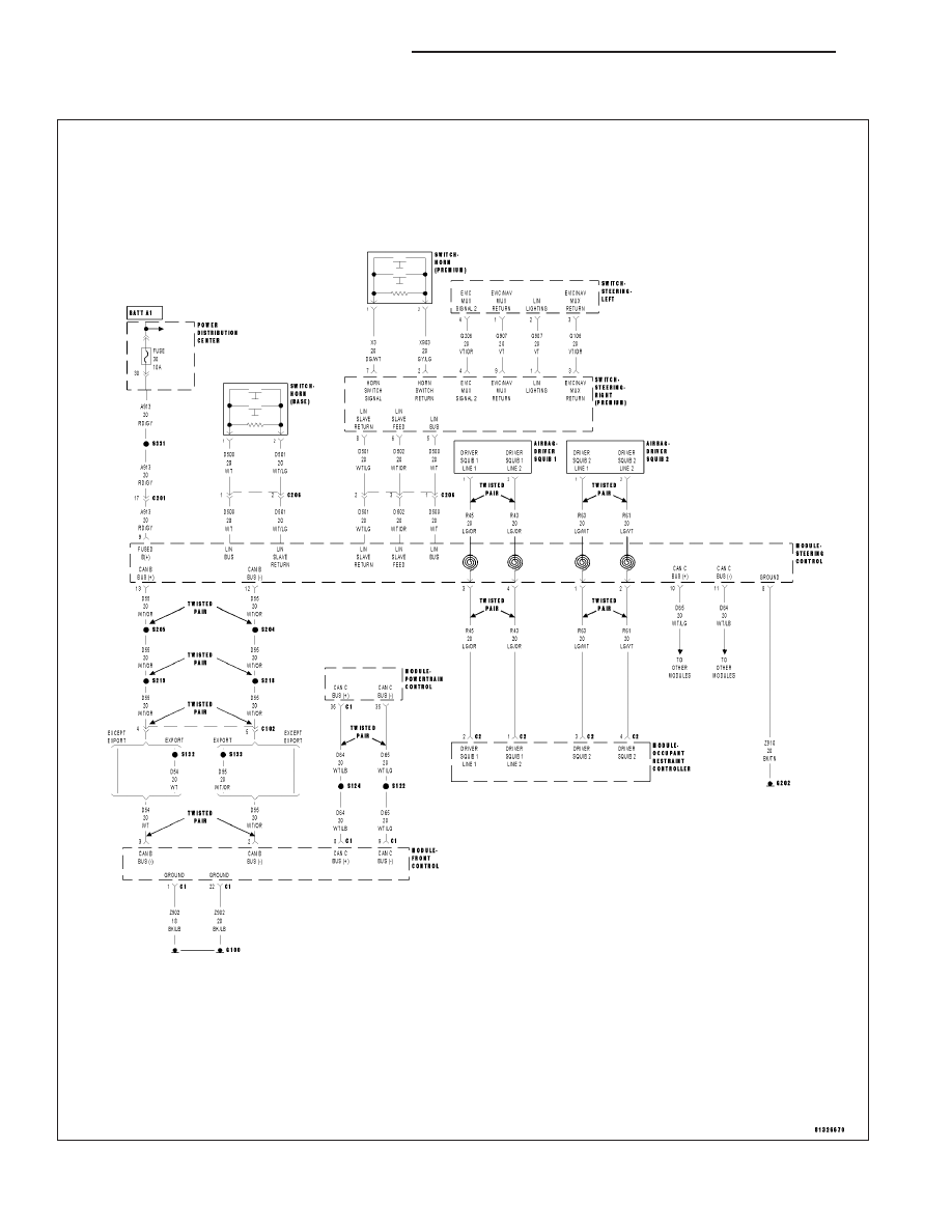
U0002–CAN C BUS OFF PERFORMANCE

For a complete wiring diagram Refer to Section 8W.

19 - 98

COLUMN ELECTRICAL DIAGNOSIS

LX

When Monitored:
Continuously.

Set Condition:
Whenever the CAN C Bus (+) or CAN C Bus (-) is open, shorted to voltage or shorted to ground.

Possible Causes

INTERMITTENT CAN C BUS OFF PERFORMANCE DTC

CAN C BUS DTCs SET IN FRONT CONTROL MODULE

(D65) CAN C BUS (+) CIRCUIT OPEN

(D64) CAN C BUS (-) CIRCUIT OPEN

STEERING CONTROL MODULE (SCM)

Diagnostic Test

1.

DTC IS ACTIVE

Ignition on, engine not running.

With the scan tool, select Clear Stored DTCs in the Steering Control Module.

Cycle the ignition from off to on at least 5 times, leaving the ignition on for a minimum of 90 seconds per cycle.

With the Scan Tool, select View DTCs in the Steering Control Module.

Does the DTC reset and/or remain active?

Yes

>> Go to 2

No

>> Go to 6

2.

CAN C BUS DTCs SET IN FRONT CONTROL MODULE

With the Scan Tool, select View DTCs in the Front Control Module (FCM).

Are there any active CAN C Bus DTCs?

Yes

>> Refer to 8 — ELECTRICAL/ELECTRONIC CONTROL MODULES — DIAGNOSIS AND TESTING for

diagnostic procedures and for further possible causes.

No

>> Go to 3

3.

(D65) CAN C BUS (+) CIRCUIT OPEN

Turn the ignition off.

Disconnect the Steering Control Module harness connector.

Disconnect the Front Control Module C1 harness connector.

Measure the resistance of the (D65) CAN C Bus (+) circuit between the Steering Control Module harness connector
and the Front Control Module C1 harness connector.

Is the resistance above 2.0 ohms?

Yes

>> Repair the (D65) CAN C Bus (+) circuit for an open.

No

>> Go to 4

LX

COLUMN ELECTRICAL DIAGNOSIS

19 - 99

4.

(D64) CAN C BUS (-) CIRCUIT OPEN

Measure the resistance of the (D64) CAN C Bus (-) circuit between the Steering Control Module harness connector
and the Front Control Module C1 harness connector.

Is the resistance above 2.0 ohms?

Yes

>> Repair the (D64) CAN C Bus (-) circuit for an open.

No

>> Go to 5

5.

STEERING CONTROL MODULE (SCM)

Inspect the wiring between the Steering Control Module harness connector and the Front Control Module harness
connector. If any problems are found, repair as necessary. If no problems are found, view repair.

Repair

Replace the Steering Control Module (SCM) in accordance with the Service Information.

6.

INTERMITTENT CAN C BUS OFF PERFORMANCE DTC

The conditions necessary to set this DTC are not present at this time.

Using the wiring diagram/schematic as a guide, inspect the wiring and connectors.

While monitoring the scan tool data relative to this circuit, wiggle test the wiring and connectors.

Look for the data to change or for the DTC to reset during the wiggle test.

Were any problems found?

Yes

>> Repair as necessary.

No

>> Test complete.

19 - 100

COLUMN ELECTRICAL DIAGNOSIS

LX

U0019–CAN B BUS CIRCUIT

For a complete wiring diagram Refer to Section 8W.

LX

COLUMN ELECTRICAL DIAGNOSIS

19 - 101


Content   ..  1818  1819  1820  1821   ..