Chrysler 300/300 Touring/300C, Dodge Magnum. Manual - part 1814


  Index      Chrysler     Chrysler 300/300 Touring/300C, Dodge Magnum - service repair manual


Search            


Content   ..  1812  1813  1814  1815   ..


Chrysler 300/300 Touring/300C, Dodge Magnum. Manual - part 1814


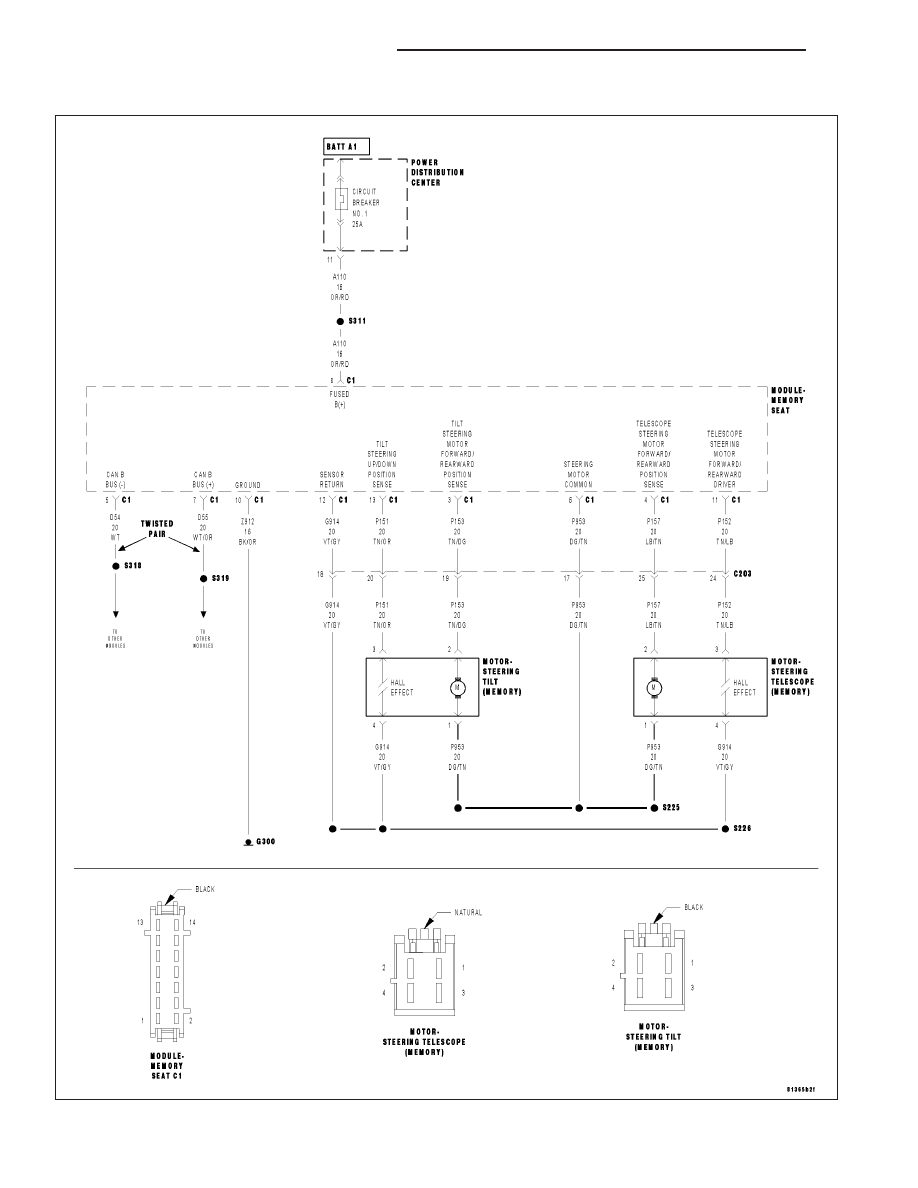
B1D92–STEERING COLUMN TILT POSITION SENSOR CIRCUIT HIGH

For a complete wiring diagram Refer to Section 8W.

19 - 74

COLUMN ELECTRICAL DIAGNOSIS

LX

Theory of Operation

The MSM input signal from the Steering Column Tilt Sensor is recognized in a specified voltage area. The input
channel is an analog to digital converter input and the sensor is a hall sensor.

When Monitored:
The hall supply voltage is switched on when the motor becomes activated.

Set Condition:
The sensed input is recognized in a defined voltage area (between 3.7 and 5.0 volts at the controller input, not
at the module input) for more than 14 mS

Possible Causes

INTERMITTENT STEERING COLUMN TILT POSITION SENSOR CIRCUIT HIGH DTC

(P151) TILT STEERING UP/DOWN POSITION SENSE CIRCUIT OPEN

(P151) TILT STEERING UP/DOWN POSITION SENSE CIRCUIT SHORT TO VOLTAGE

(P151) TILT STEERING UP/DOWN POSITION SENSE CIRCUIT SHORT TO TILT/TELESCOPE MOTOR
CIRCUIT(S)

(G914) SENSOR RETURN CIRCUIT OPEN

(G914) SENSOR RETURN CIRCUIT SHORT TO VOLTAGE

STEERING COLUMN TELESCOPE MOTOR

MEMORY SEAT MODULE (MSM)

Diagnostic Test

1.

DTC IS ACTIVE

Ignition on, engine not running.

With the Scan Tool, select Clear Stored DTCs in the Memory Seat Module.

Move the Steering Column Tilt Switch to the Up and Down positions several times, holding the switch in position for
at least 2 seconds each time.

With the Scan Tool, select View DTCs in the Memory Seat Module.

Does this DTC reset and/or remain active?

Yes

>> Go to 2

No

>> Go to 10

2.

CHECK DTC WITH HARNESS DISCONNECTED

Turn the ignition off.

Disconnect the Steering Tilt Motor harness connector.

Ignition on, engine not running.

Move the Steering Column Tilt Switch to the Up and Down positions several times.

With the Scan Tool, select Clear Stored DTCs in the Memory Seat Module.

Move the Steering Column Tilt Switch to the Up and Down positions several times, holding the switch in position for
at least 2 seconds each time.

With the Scan Tool, select View DTCs in the Memory Seat Module.

Does this DTC reset and/or remain active?

Yes

>> Go to 3

No

>> Go to 8

LX

COLUMN ELECTRICAL DIAGNOSIS

19 - 75

3.

(P151) TILT STEERING UP/DOWN POSITION SENSE CIRCUIT OPEN

Turn the ignition off.

Disconnect the Memory Seat Module (MSM) C1 connector.

Measure the resistance of the (P151) Tilt Steering Up/Down Position
Sense circuit.

Is the resistance above 5.0 ohms?

Yes

>> Repair the (P151) Tilt Steering Up/Down Position Sense cir-

cuit for an open.

No

>> Go to 4

4.

(P151) TILT STEERING UP/DOWN POSITION SENSE CIRCUIT SHORT TO VOLTAGE

Turn the ignition on.

Measure the voltage of the (P151) Tilt Steering Up/Down Position
Sense circuit.

Is there any voltage present?

Yes

>> Repair the (P151) Tilt Steering Up/Down Position Sense cir-

cuit for a short to voltage.

No

>> Go to 5

19 - 76

COLUMN ELECTRICAL DIAGNOSIS

LX

5.

(P151) TILT STEERING UP/DOWN POSITION SENSE CIRCUIT SHORT TO TILT/TELESCOPE MOTOR
CIRCUIT(S)

Turn the ignition off.

Measure the resistance between the following circuits at the Memory
Seat Module (MSM) C1 connector :

The (P151) Tilt Steering Up/Down Position Sense circuit and the

(P157) Telescope Steering Motor Forward/Rearward Driver circuit.

The (P151) Tilt Steering Up/Down Position Sense circuit and the

(P153) Tilt Steering Motor Up/Down Driver circuit.

The (P151) Tilt Steering Up/Down Position Sense circuit and the

(P953) Steering Motor Common circuit.

Is the resistance below 5.0 ohms for any of the circuit
tests?

Yes

>> Repair the (P151) Tilt Steering Up/Down Position Sense cir-

cuit for a short to the motor circuit(s).

No

>> Go to 6

6.

(G914) SENSOR RETURN CIRCUIT OPEN

Measure the resistance of the (G914) Sensor Return circuit.

Is the resistance above 5.0 ohms?

Yes

>> Repair the (G914) Sensor Return circuit for an open.

No

>> Go to 7

LX

COLUMN ELECTRICAL DIAGNOSIS

19 - 77


Content   ..  1812  1813  1814  1815   ..