Content .. 1791 1792 1793 1794 ..
Chrysler 300/300 Touring/300C, Dodge Magnum. Manual - part 1793
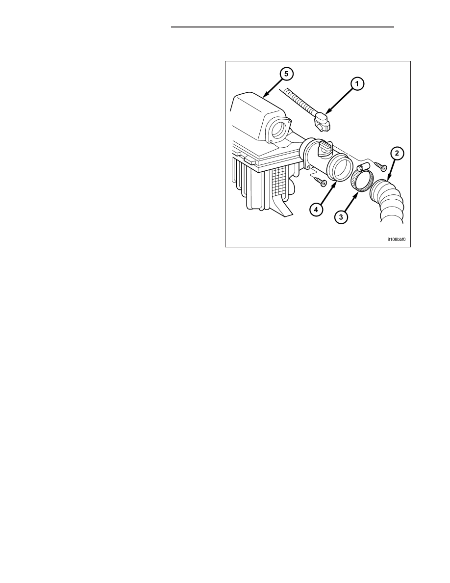
INSTALLATION
1. Position the MAF sensor (4) to air cleaner housing
(5) and install the retaining screws.
2. Connect the air intake hose (2) to the MAF sensor
and tighten clamp (3).
3. Connect the MAF wiring harness connector (1).
4. Connect negative battery cable.
14 - 246
FUEL INJECTION - DIESEL
LX