Chrysler 300/300 Touring/300C, Dodge Magnum. Manual - part 1758


  Index      Chrysler     Chrysler 300/300 Touring/300C, Dodge Magnum - service repair manual


Search            


Content   ..  1756  1757  1758  1759   ..


Chrysler 300/300 Touring/300C, Dodge Magnum. Manual - part 1758


4. Install inlet supply line clamp using Fuel Line Pliers

9539.

5. Install return line clamp using Fuel Line Pliers

9539.

CAUTION: Do not crimp or bend fuel line. Inspect
sealing cone at line; replace line if compression
exists.

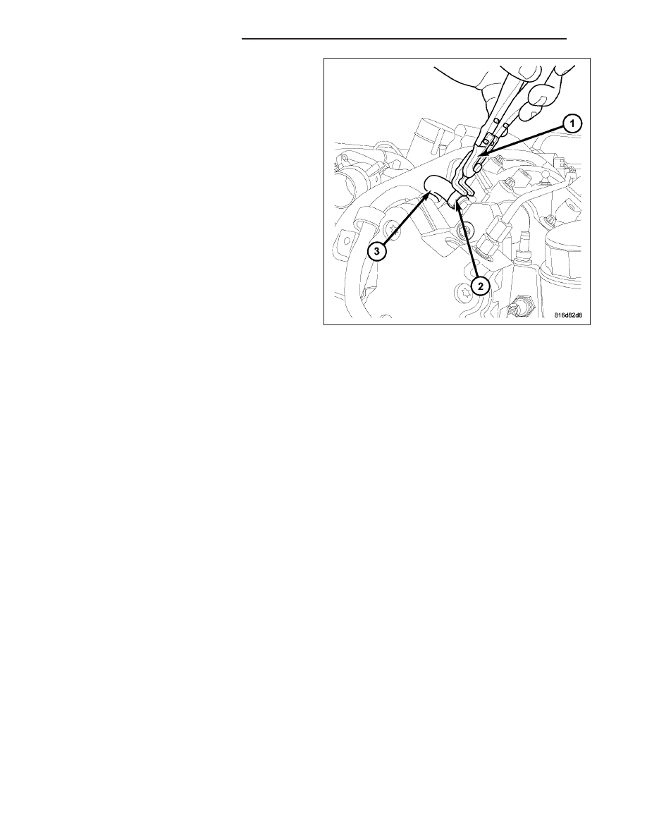
6. Install high pressure fuel line retaining nuts. Torque

nuts to 33 N·m (24 ft.lbs.).

7. Install high pressure line support bracket.

8. Install negative battery cable.

9. Install the engine cover.

10. Start engine and check for leaks.

14 - 106

FUEL DELIVERY - DIESEL

LX

SENSOR-WATER IN FUEL

DESCRIPTION

The water in fuel sensor (WIF) is located in the fuel filter housing The sensor detects the presence of water in the
fuel. If water is present in the fuel, a signal is sent to the ECM and the ECM signals the instrument cluster, over the
CAN bus, to illuminate the water in fuel warning.

OPERATION

The non-dielectric properties of the water allow the sensors probes to close the electronic circuit when water is
present in the system. When diesel fuel is present in the system, it’s dielectric (does not conduct electricity well)
properties do not allow any electrical contact between the probes. A 12V power signal is always present in order to
illuminate the indicator on the instrument cluster.

REMOVAL

1. Disconnect the negative battery cable.

2. Remove the engine cover.

NOTE: Capture and store any fuel spillage in appropriate containers

3. Disconnect the water in fuel (WIF) electrical connector.

4. Remove the WIF sensor retaining screws.

5. Twist the WIF sensor so the tabs clear the retaining bracket.

6. Gently pry up on the sensor and remove.

INSTALLATION

NOTE: Remove any dirt and debris around the fuel filter assembly using a suitable solvent or compressed
air. Area around the fuel filter assembly must be clean and dry.

1. Lubricate the water in fuel (WIF) sensor Orings with clean diesel fuel.

2. Insert the WIF sensor into the fuel filter assembly and twist the sensor until the retaining holes align with the

retaining bracket on the fuel filter assembly.

3. Install the retaining screws. Tighten to 1.5 N·m (13 in. lbs.).

4. Connect the WIF wiring harness connector.

5. Connect the negative battery cable.

6. Start the engine, allow to warm, turn engine off and inspect for leaks.

7. Install engine cover.

LX

FUEL DELIVERY - DIESEL

14 - 107

FITTING-QUICK CONNECT

DESCRIPTION

Different types of quick-connect fittings are used to attach the various fuel system components, lines and tubes.
These are: a single-button type shown above. a two-button type, a pinch type, a single-tab type, a two-tab type or
a plastic retainer ring type. Some are equipped with safety latch clips. Some may require the use of a special tool
for disconnection and removal. Refer to Quick-Connect Fittings Removal/Installation for more information.

CAUTION: Before separating a quick-connect fitting, pay attention to what type of fitting is being used by
referring to Quick-Connect Fitting Removal. This will prevent unnecessary fitting or fitting latch breakage.

CAUTION: The interior components (o-rings, clips) of quick-connect fittings are not serviced separately, but
new plastic spacers and latches are available for some types. If service parts are not available, do not
attempt to repair the damaged fitting or fuel line (tube). If repair is necessary, replace the complete fuel line
(tube) assembly.

STANDARD PROCEDURE - QUICK-CONNECT FITTINGS

Different types of quick-connect fittings are used to attach the various fuel system components, lines and tubes.
These are: a single-button type, a two-button type, a pinch type, a single-tab type, a two-tab type or a plastic
retainer ring type. Some are equipped with safety latch clips. Some may require the use of a special tool for dis-
connection and removal.

DISCONNECTING

WARNING: The fuel system is under a constant pressure (even with engine off). Before servicing any fuel
system hose, fitting or line, fuel system pressure must be released. Refer to fuel system pressure release
procedure.

CAUTION: Before separating a quick-connect fitting, pay attention to what type of fitting is being used by
referring to Quick-Connect Fitting Removal. This will prevent unnecessary fitting or fitting latch breakage.

CAUTION: The interior components (o-rings, clips) of quick-connect fittings are not serviced separately, but
new plastic spacers and latches are available for some types. If service parts are not available, do not
attempt to repair the damaged fitting or fuel line (tube). If repair is necessary, replace the complete fuel line
(tube) assembly.

1. Perform fuel pressure release procedure. (Refer to 14 - FUEL SYSTEM/FUEL DELIVERY - STANDARD PRO-

CEDURE).

2. Disconnect negative battery cable from battery.

3. Clean fitting of any foreign material before disassembly.

14 - 108

FUEL DELIVERY - DIESEL

LX

4. Single-Button Type Fitting: This type of fitting is

equipped with a single push-button (2) located on
the quick-connect fitting.

5. The push-button is attached to two internal latches

(1). To disconnect, press on push-button with your
thumb and unlatch fitting from fuel line. Tools are
not required for disconnection. DO NOT ATTEMPT
TO PRY OR PULL UP ON PUSH-BUTTON.
LATCHES WILL BE BROKEN.

LX

FUEL DELIVERY - DIESEL

14 - 109


Content   ..  1756  1757  1758  1759   ..