Chrysler 300/300 Touring/300C, Dodge Magnum. Manual - part 1720


  Index      Chrysler     Chrysler 300/300 Touring/300C, Dodge Magnum - service repair manual


Search            


Content   ..  1718  1719  1720  1721   ..


Chrysler 300/300 Touring/300C, Dodge Magnum. Manual - part 1720


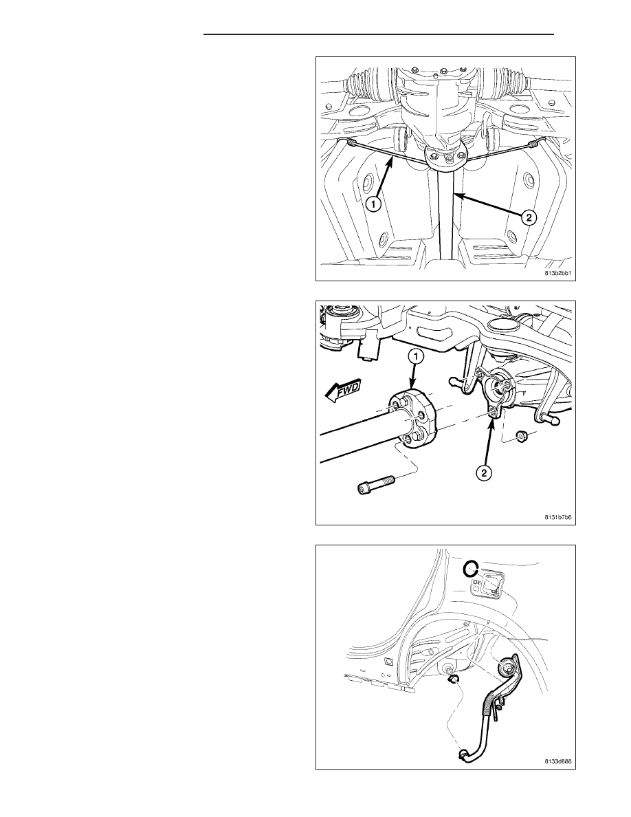
25. Remove bungee cord (1) supporting propeller

shaft (2).

26. Align propeller shaft index marks (3) placed upon

removal. Install propeller shaft rear coupler-to-axle
flange bolts and nuts by hand. Tighten propeller
shaft rear coupler-to-axle flange bolts to 81 N·m
(60 ft. lbs.).

27. Install fuel filler tube. (Refer to 14 - FUEL SYS-

TEM/FUEL DELIVERY/FUEL TANK FILLER TUBE
- INSTALLATION)

13 - 80

FRAME & BUMPERS

LX

28. Clip left rear wheel speed sensor cable (3) to

routing clip (1) near body connector.

29. Match left rear wheel speed sensor connector (4)

to right sensor connector (3) to make one connec-
tor.

30. Insert speed sensor connectors (3 and 4) into

body wiring harness connector (1) located in lug-
gage compartment floor pan (2). When installing
connector, make sure retaining clip on body con-
nector is properly in place and sensor connector
cannot be pulled out.

31. If equipped with standard or premium disc brakes,

on each rear disc brake:

a. Push caliper guide pins into caliper adapter to

clear caliper mounting bosses when installing.

b. Guide caliper and brake hose down through

rear suspension, then slide caliper over brake
pads and onto caliper adapter (3).

c.

CAUTION: Extreme caution should be taken not to
cross-thread caliper guide pin bolts (2) when they
are installed.Align caliper mounting holes with
guide pins, then install guide pin bolts (2). While
holding guide pins from turning, tighten bolts to
31 N·m (23 ft. lbs.) torque.

d. Make sure brake hose is properly routed and

will not come in contact with suspension
components.

LX

FRAME & BUMPERS

13 - 81

32. If equipped with SRT8 disc brakes, at each rear disc brake, support spring link using a transmission jack or

other appropriate jack as indicated in removal procedure. (Refer to 13 - FRAME & BUMPERS/FRAME/BUSH-
ING - REMOVAL)

33. If equipped with SRT8 disc brakes, on each rear

disc brake, slide caliper with pads (2) over brake
rotor and align with knuckle.

34. If equipped with SRT8 disc brakes, on each rear

disc brake, install caliper mounting bolts (1).
Tighten bolts to 130 N·m (96 ft. lbs.) torque.

35. If equipped with SRT8 disc brakes, on each rear

disc brake, remove jack from under spring link.

36. Route parking brake cable above rear crossmem-

ber, then slide cable (1, 3) through equalizer (2)
above rear axle differential (once installed).

13 - 82

FRAME & BUMPERS

LX

NOTE: Due to short travel and low spring tension,
it is not necessary to lock-out parking brake lever
to service parking brake components.

37. Connect front parking brake cable (5) at connec-

tor (3) to right rear parking brake cable (4).

38. Insert front parking brake cable routing bracket

locating pin into front flange of crossmember (3),
then install screw (2) fastening cable (1) routing
bracket to rear crossmember.

39. Install

rear

exhaust

system

(2)

(dual-outlet

exhaust shown in figure). (Refer to 11 - EXHAUST
SYSTEM - INSTALLATION)

LX

FRAME & BUMPERS

13 - 83


Content   ..  1718  1719  1720  1721   ..