Chrysler 300/300 Touring/300C, Dodge Magnum. Manual - part 1721


  Index      Chrysler     Chrysler 300/300 Touring/300C, Dodge Magnum - service repair manual


Search            


Content   ..  1719  1720  1721  1722   ..


Chrysler 300/300 Touring/300C, Dodge Magnum. Manual - part 1721


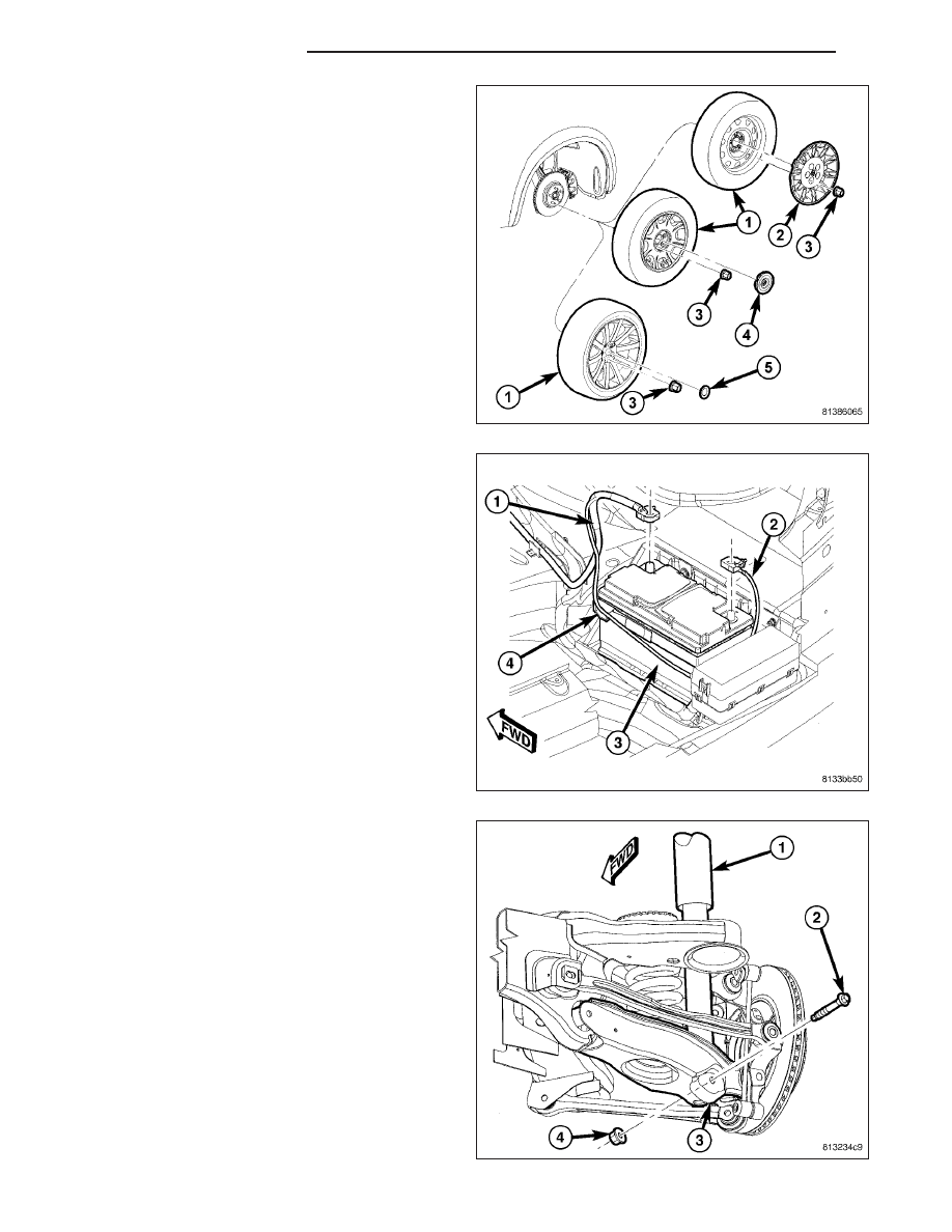
40. Install tire and wheel assemblies (1). Tighten

wheel mounting nuts (3) to 150 N·m (110 ft. lbs.).
(Refer to 22 - TIRES/WHEELS - INSTALLATION)

41. Lower vehicle until rear wheels are just above

floor level.

42. Apply parking brake lever. Release lever, then

reapply.

43. Check to make sure rear wheels will not rotate

with lever applied.

44. Lower vehicle.

45. Connect battery negative cable (2) to battery post.

It is important that this is performed properly.
(Refer to 8 - ELECTRICAL/BATTERY SYSTEM -
STANDARD PROCEDURE)

46. Pump brake pedal several times to ensure vehicle

has a firm brake pedal before moving vehicle.

47. Position vehicle on alignment rack/drive-on lift.

Raise vehicle as necessary to access mounting
bolts.

48. Tighten shock absorber lower mounting bolt nuts

(4) to 72 N·m (53 ft. lbs.).

49. Perform wheel alignment, paying special attention

to thrust angle. If rear crossmember needs to be
shifted to align thrust angle, try to avoid compro-
mising tension link clearance (Refer to Step 22).
(Refer to 2 - SUSPENSION/WHEEL ALIGNMENT
- STANDARD PROCEDURE)

13 - 84

FRAME & BUMPERS

LX

BUSHING-REAR CROSSMEMBER SPRING LINK

REMOVAL

1. Raise and support vehicle. (Refer to LUBRICATION & MAINTENANCE/HOISTING - STANDARD PROCEDURE)

2. Access and remove rear spring on side of repair. (Refer to 2 - SUSPENSION/REAR/SPRING - REMOVAL)

3. Export Only – If servicing right side bushing, dis-

connect headlamp leveling sensor (1) link at spring
link (3).

4. Remove bolt and nut (1) fastening spring link (4) to

crossmember.

5. Position spring link downward, away from bushing

in crossmember.

LX

FRAME & BUMPERS

13 - 85

NOTE: Prior to using Press (3), Special Tool
C-4212F, lubricate screw-drive threads to provide
ease of use and promote tool longevity.

6. Assemble tools over bushing as shown (See list).

Ensure Receiver, Special Tool 9032-1, sets against
crossmember and not welds.

(2) Remover 9032-2

(3) Press C-4212F

(4) Receiver 9032-1

7. Tighten Press screw-drive, pressing bushing out of

crossmember.

INSTALLATION

1. Position bushing (1) over rear of crossmember

bushing bore.

2. Assemble tools over bushing and crossmember as

shown (See list). Ensure Receiver, Special Tool
9032-3, is positioned to avoid welds on rear of
crossmember bushing bore.

(2) Remover/Installer 9032-2

(3) Press C-4212F

(4) Receiver 9032-3

3. Tighten Press screw-drive, pressing bushing into

crossmember.

Install

bushing

until

screw-drive

stops, when bushing contacts Receiver on opposite
side of crossmember.

4. Remove tools.

5. Swing spring link up to bushing in crossmember

and install bolt and nut (1) fastening spring link (4)
to crossmember. Do not tighten bolt at this time.

13 - 86

FRAME & BUMPERS

LX

6. Export Only – If servicing right side bushing, con-

nect headlamp leveling sensor (1) link at spring link
(3).

7. Install rear spring as well as all components neces-

sary to access it. (Refer to 2 - SUSPENSION/
REAR/SPRING - INSTALLATION)

8. Lower vehicle.

9. Position vehicle on alignment rack/drive-on lift.

Raise vehicle as necessary to access mounting
bolt.

10. Tighten spring link bolt (1) at crossmember to 108

N·m (80 ft. lbs.).

11. Perform wheel alignment. (Refer to 2 - SUSPEN-

SION/WHEEL

ALIGNMENT

-

STANDARD

PROCEDURE)

LX

FRAME & BUMPERS

13 - 87


Content   ..  1719  1720  1721  1722   ..