Chrysler 300/300 Touring/300C, Dodge Magnum. Manual - part 1712


  Index      Chrysler     Chrysler 300/300 Touring/300C, Dodge Magnum - service repair manual


Search            


Content   ..  1710  1711  1712  1713   ..


Chrysler 300/300 Touring/300C, Dodge Magnum. Manual - part 1712


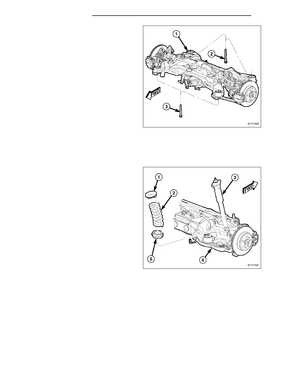
25. Remove both front (3) and both rear (2) mounting

bolts fastening crossmember (1) in place.

26. Slowly lower crossmember using jack. Do not lower jack at a fast rate. Lower just enough to allow propeller

shaft removal from rear axle differential. Do not lower jack any further than necessary. Slide propeller shaft
out of rear axle differential and allow bungee cord previously installed to support.

27. Lower crossmember until crossmember is at a comfortable working level to access bushings. Support rear sus-

pension assembly using jack stands to help stabilize assembly during bushing service.

28. Remove coil springs (2) with isolators (1 and 5)

from spring links (4).

13 - 48

FRAME & BUMPERS

LX

29. As an installation reference, carefully mark loca-

tion of bushing requiring removal on crossmember
(around bushing can flange) using a marker or
crayon. Do not use a scratch awl to mark
location.

30. Remove nut and bolt (1) fastening compression

link (3) to crossmember.

31. Remove travel limiter (2) from bushing inner metal

sleeve (1). To do so, use an appropriate grinding
tool to remove inner metal sleeve material until
limiter can be safely removed.

LX

FRAME & BUMPERS

13 - 49

32. Slide Support (2), Special Tool 9031-9, into end of

crossmember (3) surrounding bushing bore as
shown.

33. Snug set-screws (1) securing Support (2) to

crossmember.

34. Insert Brace (1), Special Tool 9031-10, between

Support 9031-9 (3) and bushing bore flange (2)
matching step in Brace to bore flange.

35. Snug set-screws (2) against Brace 9031-10. Do

not overtighten set-screws as they will distort
and bend bushing bore flange.

13 - 50

FRAME & BUMPERS

LX

NOTE: Prior to using Press (1), Special Tool
C-4212F, lubricate screw-drive threads to provide
ease of use and promote tool longevity.

36. Assemble tools (See following list) over bushing

as shown. Ensure Remover lies between ridges
(3) on bushing to properly contact bushing can.

(1) Press C-4212F

(2) Remover 9031-5A

(4) Receiver 9031-8A

37. Tighten Press (1) screw-drive, pressing bushing

out of crossmember.

38. Remove all tools.

INSTALLATION

CAUTION: Prior to bushing installation, inspect
the bushing to make sure it is the correct side
bushing for the job. Left side bushings have the
travel limiter (1) tipped to the right in relationship
to the bushing (4) can flange as shown. Right side
bushings have the travel limiter (2) tipped to the
left in relationship to the bushing (3) can flange as
shown. Once installed, the travel limiters with face
slightly outward from straight-ahead position.

CAUTION: It is very important that bushing be installed in same position as original to maintain vehicle ride
quality and bushing longevity. That is why bushing, once installed, needs to closely match reference marks
applied upon removal of original bushing.

1. Position bushing on crossmember bushing bore aligning bushing can flange with reference marks applied during

removal.

LX

FRAME & BUMPERS

13 - 51


Content   ..  1710  1711  1712  1713   ..