Content .. 1675 1676 1677 1678 ..
Chrysler 300/300 Touring/300C, Dodge Magnum. Manual - part 1677
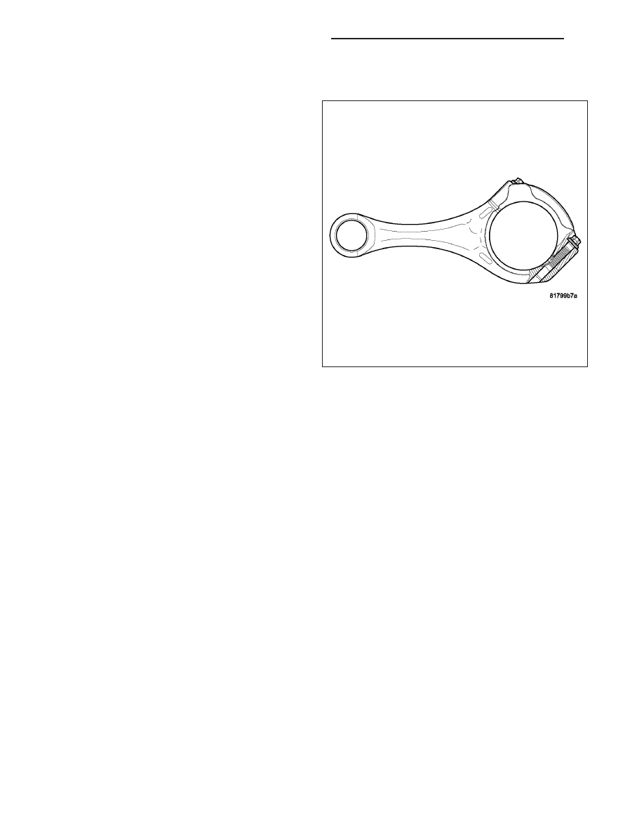
CONNECTING RODS
CAUTION: Connecting rods must be replaced once
the end caps are loosened. All six must have the
same weight and the same number. Replacement
connecting rods will only be supplied in sets of
six. When assembling the connecting rod, be sure
to paint mark or scribe mark each of the connect-
ing rods and caps before installation, for align-
ment purposes later.
NOTE: Do Not lubricate the new connecting rod
bolts. They are already coated with a anti scuff
treatment.
Connecting rods are supplied in sets of six since they
all must be of the same weight category. Max allow-
able weight difference is 5 gr.
1. Assemble bearing shells and bearing caps to their
respective connecting rods ensuring that the serra-
tions on the cap and reference marks are aligned.
2. Tighten connecting cap bolts to 20 N·m (15 ft. lbs.).
3. Without loosening connecting rod bolts, tighten all
bolts to 40 N·m (30 ft.lbs.).
4. Using a torque angle gauge, tighten each bolt an additional 90°.
INSTALLATION
PISTON PIN INSTALLATION
1. Secure connecting rod in soft jawed vice.
2. Lubricate piston pin and piston with clean engine oil.
3. Position piston on connecting rod.
CAUTION: Ensure arrow on piston crown and the bearing cap numbers on the connecting rod are on the
opposite side.
4. Install piston pin.
5. Install clips in piston to retain piston pin.
9 - 2732
ENGINE - 3.0L TD SERVICE INFORMATION
LX