Chrysler 300/300 Touring/300C, Dodge Magnum. Manual - part 160


  Index      Chrysler     Chrysler 300/300 Touring/300C, Dodge Magnum - service repair manual


Search            


Content   ..  158  159  160  161   ..


Chrysler 300/300 Touring/300C, Dodge Magnum. Manual - part 160


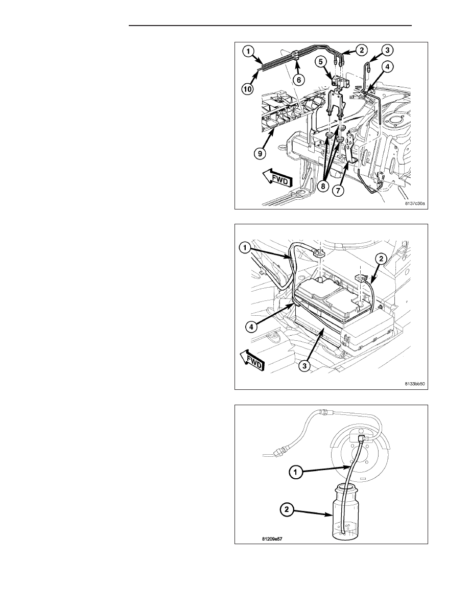
3. Install brake tubes (1, 2, 3 and 10) at junction block

(5). Tighten tube nuts to 20 N·m (177 in. lbs.)
torque.

4. Remove brake pedal holding tool.

5. Connect battery negative cable (2) to battery post.

It is important that this is performed properly. (Refer
to 8 - ELECTRICAL/BATTERY SYSTEM - STAN-
DARD PROCEDURE)

6. Fill and bleed (1) base brake hydraulic system.

(Refer to 5 - BRAKES - STANDARD PROCE-
DURE)

7. Road test vehicle to verify proper operation of

brakes.

5 - 82

BRAKES - BASE

LX

MASTER CYLINDER

DESCRIPTION

There are two different master cylinder designs used depending on whether the vehicle is an early build vehicle or
a later build vehicle. To simplify the differentiation between early and later brake systems, for this service information
they are referred to as the MK25 master cylinder and the MK25E master cylinder. This is because the master cyl-
inders change when the availability of the antilock brake systems change. Early build vehicles use MK25 ABS and
later build vehicles use MK25E ABS. Be aware that these type master cylinders are also used on vehicles that are
not equipped with antilock brakes.

Although similar in function and appearance, the
MK25E master cylinder does not have a pressure
switch located on the bottom and it has larger outlet
ports with SAE flares. The primary port (1) is designed
for 5/16 inch (8 mm) tubing and the secondary port (2)
is designed for 1/4 inch (6.25 mm) tubing.

Both standard MK25 and MK25E master cylinders have 25.4 mm bores. Although appearing and serviced the same,
the master cylinder used on SRT8 and Police vehicles has a larger 27 mm bore. The SRT8 and Police Package
master cylinder can be identified by a green dot placed on the body of the master cylinder.

On SRT8 vehicles with the MK25 ABS system, the
brake pressure sensor (3) which normally mounts to
the bottom of the master cylinder is mounted to the
primary brake tube (3) near the master cylinder (1).

LX

BRAKES - BASE

5 - 83

STANDARD PROCEDURE

MASTER CYLINDER BLEEDING - MK25

NOTE: Vehicles that are not equipped with ABS also use this master cylinder, but in an effort to simplify the
differentiation between early and late brake systems it is being referred to as the MK25 master cylinder.

CAUTION: When clamping master cylinder in vise, only clamp master cylinder by its mounting flange. Do
not clamp master cylinder piston rod, reservoir, seal or body.

1. Clamp master cylinder in a vise.

2. Attach special tools for bleeding master cylinder in

the following fashion:

a. Thread one Adapter (3), Special Tool 8822–2,

in each outlet port. Tighten Adapters to 14 N·m
(124 in. lbs.) torque.

b. Thread a Bleeder Tube (1), Special Tool

8358–1, into each Adapter. Tighten each tube
to 14 N·m (124 in. lbs.) torque. Flex each
bleeder tube and place open end into mouth of
fluid reservoir as far down as possible.

NOTE: Make sure open ends of bleeder tubes stay
below surface of brake fluid once reservoir is filled
to proper level.

3. Fill brake fluid reservoir (1) to the MAX level with

Mopar

T

brake fluid or equivalent conforming to

DOT 3 specifications. Make sure fluid level is
above tips of bleeder tubes in reservoir to ensure
no air is ingested during bleeding.

5 - 84

BRAKES - BASE

LX

4. Using a wooden dowel as a pushrod (2), slowly

depress master cylinder pistons, then release pres-
sure, allowing pistons to return to released position.
Repeat several times until all air bubbles are
expelled. Make sure fluid level stays above tips of
bleeder tubes in reservoir while bleeding.

5. Remove bleeder tubes (1) and adapters (3) from

master cylinder outlet ports, then plug outlet ports
and install fill cap on reservoir.

6. Remove master cylinder from vise.

7. Install master cylinder on vehicle. (Refer to 5 -

BRAKES

-

BASE/HYDRAULIC/MECHANICAL/

MASTER CYLINDER - INSTALLATION)

MASTER CYLINDER BLEEDING - MK25E

NOTE: Vehicles that are not equipped with ABS also use this master cylinder, but in an effort to simplify the
differentiation between early and late brake systems it is being referred to as the MK25E master cylinder.

CAUTION: When clamping master cylinder in vise, only clamp master cylinder by its mounting flange. Do
not clamp master cylinder piston rod, reservoir, seal or body.

1. Clamp master cylinder in a vise.

CAUTION: When installing Adapters in master cyl-
inder, do not overtighten. Damage to master cylin-
der could occur.

NOTE: Adapters 9748-1 and 9748-2 are not inter-
changeable. To avoid mix-up of Adapters, 9748–1
is silver while 9748–2 is black.

2. Attach special tools for bleeding master cylinder in

following fashion:

a. Thread Adapter (3), Special Tool 9748–2, into

primary outlet port. Tighten Adapter to 14 N·m
(124 in. lbs.).

b. Thread Adapter (4), Special Tool 9748–1, into

secondary outlet port. Tighten Adapter to 14
N·m (124 in. lbs.).

c. Thread a Bleeder Tube (2), Special Tool

8358–1, into each Adapter. Tighten each tube
to 14 N·m (124 in. lbs.). Flex each bleeder tube and place open end into mouth of fluid reservoir as far down
as possible.

LX

BRAKES - BASE

5 - 85


Content   ..  158  159  160  161   ..