Chrysler 300/300 Touring/300C, Dodge Magnum. Manual - part 159


  Index      Chrysler     Chrysler 300/300 Touring/300C, Dodge Magnum - service repair manual


Search            


Content   ..  157  158  159  160   ..


Chrysler 300/300 Touring/300C, Dodge Magnum. Manual - part 159


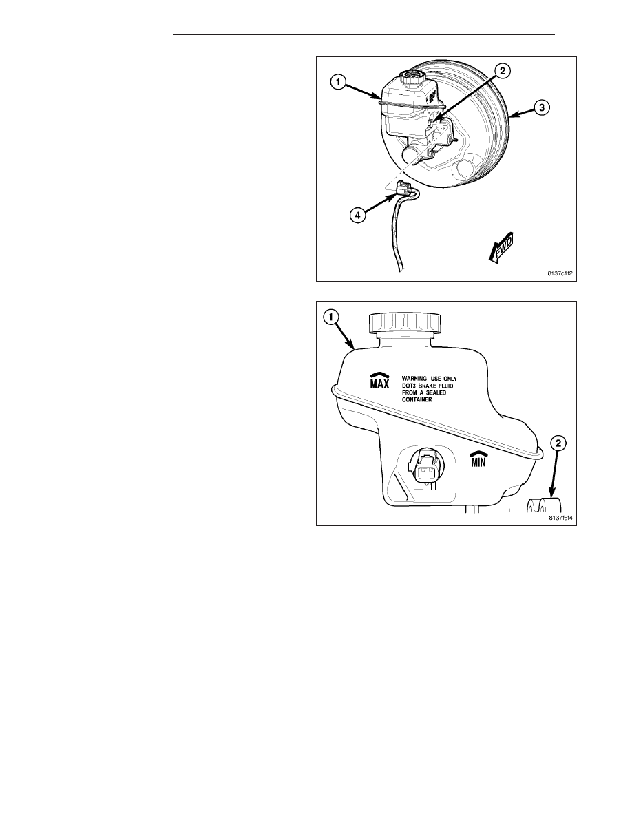
4. Connect wiring harness connector (4) to brake fluid

level sensor (2) mounted in brake fluid reservoir
(1).

5. Fill master cylinder fluid reservoir (1) with clean,

fresh Mopar

T

Brake Fluid or equivalent.

6. Install access panel in cowl area.

WARNING: Be certain a firm brake pedal is
achieved prior to attempting vehicle operation. If a
firm brake pedal cannot be achieved, bleed entire
brake hydraulic system and check for leaks. (refer
to 5 - brakes - standard procedure)

7. Road test vehicle to ensure proper operation of

brakes.

5 - 78

BRAKES - BASE

LX

JUNCTION BLOCK

DESCRIPTION

A junction block is used on vehicles that are not equipped with antilock brakes (ABS) allowing use of the same
brake tubes on all applications. The junction block is located in the engine compartment, in front of the right wheel
well. The junction block mounts in the same location as the ABS integrated control unit (ICU) does on vehicles with
ABS.

It has six threaded ports to which the brake tubes connect. Two are for the brake tubes coming from the master
cylinder. The remaining four ports are for the brake tubes going to each wheel brake assembly.

The junction block contains a proportioning valve. The proportioning valve is not serviced separately from the junc-
tion block. For more information on the proportioning valve, (Refer to 5 - BRAKES/HYDRAULIC/MECHANICAL/
PROPORTIONING VALVE - DESCRIPTION)

OPERATION

The junction block distributes the brake fluid coming from the master cylinder primary and secondary ports to the
four brake tubes leading to the wheel brakes. Since the junction block mounts in the same location as the ABS
integrated control unit (ICU), it allows for the common use of brake tubes on the vehicle whether it is equipped with
or without ABS.

The junction block includes a rear brake proportioning valve. Placed in the fluid flow passages leading to the rear
brake tube ports, it balances front-to-rear braking. (Refer to 5 - BRAKES - BASE/HYDRAULIC/MECHANICAL/PRO-
PORTIONING VALVE - OPERATION)

REMOVAL

NOTE: Before proceeding, (Refer to 5 - BRAKES - WARNING) (Refer to 5 - BRAKES - CAUTION).

1. Disconnect and isolate battery negative cable (2)

from battery post.

2. Using a brake pedal holding tool, depress brake

pedal past its first inch of travel and hold it in this
position. Holding pedal in this position will isolate
master cylinder from hydraulic brake system and
will not allow brake fluid to drain out of brake fluid
reservoir while brake lines are open.

LX

BRAKES - BASE

5 - 79

3. Remove brake tubes (1, 2, 3 and 10) at junction

block (5).

4. Remove remaining brake tubes (1 and 3) at junc-

tion block (5).

5. Pull up on junction block (5) and remove from

mounting grommets (8).

5 - 80

BRAKES - BASE

LX

INSTALLATION

1. Install junction block (5), pushing mounting bracket

down into mounting grommets (8) located in body
of vehicle.

2. Install brake tubes to rear (1 and 3) at hydraulic

control unit. Tighten tube nuts to 20 N·m (177 in.
lbs.) torque.

LX

BRAKES - BASE

5 - 81


Content   ..  157  158  159  160   ..