Chrysler 300/300 Touring/300C, Dodge Magnum. Manual - part 1127


  Index      Chrysler     Chrysler 300/300 Touring/300C, Dodge Magnum - service repair manual


Search            


Content   ..  1125  1126  1127  1128   ..


Chrysler 300/300 Touring/300C, Dodge Magnum. Manual - part 1127


3.

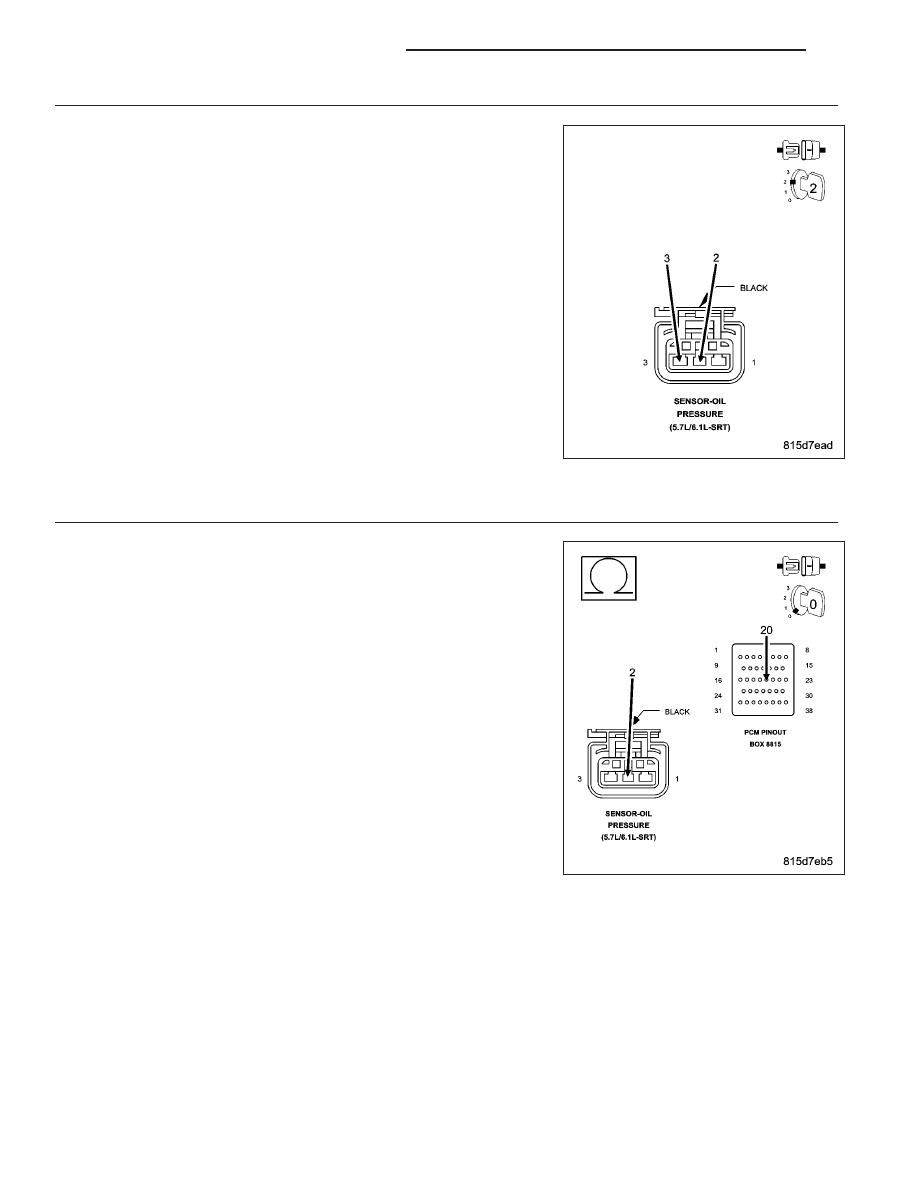
ENGINE OIL PRESSURE SENSOR

Turn the ignition off.

Connect the PCM harness connectors.

Ignition on, engine not running.

With a scan tool, monitor the Engine Oil Pressure Sensor voltage.

Connect a jumper wire between the (K900) Sensor Ground circuit and
the (G6) Engine Oil Pressure Signal circuit.

NOTE: Engine Oil Pressure voltage should change from approxi-
mately 4.5 volts to less than 0.5 of a volt.

Is the voltage reading within the listed specification when the
jumper wire is installed?

Yes

>> Remove the Engine Oil Pressure sensor and ensure the oil

passage/port is free from any blockage. If OK, replace the
Engine Oil Pressure Sensor.

Perform the POWERTRAIN VERIFICATION TEST. (Refer to
9 - ENGINE - STANDARD PROCEDURE)

No

>> Go To 4

NOTE: Remove the jumper wire before continuing.

4.

EXCESSIVE RESISTANCE IN THE (G6) ENGINE OIL PRESSURE SIGNAL CIRCUIT

Turn the ignition off.

Disconnect the PCM harness connectors.

CAUTION: Do not probe the PCM harness connectors. Probing the
PCM harness connectors will damage the PCM terminals resulting
in poor terminal to pin connection. Install Miller Special Tool #8815
to perform diagnosis.
Measure the resistance of the (G6) Engine Oil Pressure Signal circuit
from the Engine Oil Pressure Sensor harness connector to the appro-
priate terminal of special tool #8815.

Is the resistance below 5.0 ohms?

Yes

>> Go To 5

No

>> Repair the excessive resistance in the (G6) Engine Oil

Pressure Signal circuit.

Perform the POWERTRAIN VERIFICATION TEST. (Refer to
9 - ENGINE - STANDARD PROCEDURE)

9 - 532

ENGINE ELECTRICAL DIAGNOSTICS

LX

5.

(G6) ENGINE OIL PRESSURE SIGNAL CIRCUIT SHORTED TO GROUND

Measure the resistance between ground and the (G6) Engine Oil Pres-
sure Signal circuit in the Engine Oil Pressure Sensor harness connec-
tor.

Is the resistance below 100 ohms?

Yes

>> Repair the short to ground in the (G6) Engine Oil Pressure

Signal circuit.

Perform the POWERTRAIN VERIFICATION TEST. (Refer to
9 - ENGINE - STANDARD PROCEDURE)

No

>> Go To 6

6.

EXCESSIVE RESISTANCE IN THE (F856) 5–VOLT SUPPLY CIRCUIT

Measure the resistance of the (F856) 5-volt Supply circuit from the
Engine Oil Pressure Sensor harness connector to the appropriate ter-
minal of special tool #8815.

Is the resistance below 5.0 ohms?

Yes

>> Go To 7

No

>> Repair the excessive resistance in the (F856) 5-volt Supply

circuit.

Perform the POWERTRAIN VERIFICATION TEST. (Refer to
9 - ENGINE - STANDARD PROCEDURE)

LX

ENGINE ELECTRICAL DIAGNOSTICS

9 - 533

7.

(F856) 5-VOLT SUPPLY SHORTED TO GROUND

Measure the resistance between ground and the (F856) 5-volt Supply
circuit in the Engine Oil Pressure Sensor harness connector.

Is the resistance below 100 ohms?

Yes

>> Repair the short to ground in the (F856) 5-volt Supply cir-

cuit.

Perform the POWERTRAIN VERIFICATION TEST. (Refer to
9 - ENGINE - STANDARD PROCEDURE)

No

>> Go To 8

8.

EXCESSIVE RESISTANCE IN THE (K900) SENSOR GROUND CIRCUIT

Measure the resistance of the (K900) Sensor Ground circuit from the
Engine Oil Pressure Sensor harness connector to the appropriate ter-
minal of special tool #8815.

Is the resistance below 5.0 ohms?

Yes

>> Go To 9

No

>> Repair the excessive resistance in the (K900) Sensor

Ground circuit.

Perform the POWERTRAIN VERIFICATION TEST. (Refer to
9 - ENGINE - STANDARD PROCEDURE)

9 - 534

ENGINE ELECTRICAL DIAGNOSTICS

LX

9.

PCM

NOTE: Before continuing, check the PCM harness connector terminals for corrosion, damage, or terminal
push out. Repair as necessary.
Using the schematics as a guide, inspect the wire harness and connectors. Pay particular attention to all Power and
Ground circuits.

Were there any problems found?

Yes

>> Repair as necessary.

Perform the POWERTRAIN VERIFICATION TEST. (Refer to 9 - ENGINE - STANDARD PROCEDURE)

No

>> Replace and program the Powertrain Control Module per Service Information.

Perform the POWERTRAIN VERIFICATION TEST. (Refer to 9 - ENGINE - STANDARD PROCEDURE)

LX

ENGINE ELECTRICAL DIAGNOSTICS

9 - 535


Content   ..  1125  1126  1127  1128   ..