Chrysler 300/300 Touring/300C, Dodge Magnum. Manual - part 1125


  Index      Chrysler     Chrysler 300/300 Touring/300C, Dodge Magnum - service repair manual


Search            


Content   ..  1123  1124  1125  1126   ..


Chrysler 300/300 Touring/300C, Dodge Magnum. Manual - part 1125


4.

(G6) ENGINE OIL PRESSURE SIGNAL CIRCUIT SHORTED TO GROUND

Turn the ignition off.

Disconnect the PCM harness connectors.

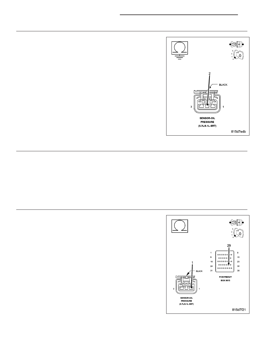
Measure the resistance between ground and the (G6) Engine Oil Pres-
sure Signal circuit in the Engine Oil Pressure Sensor harness connec-
tor.

Is the resistance below 100 ohms?

Yes

>> Repair the short to ground in the (G6) Engine Oil Pressure

Signal circuit.

Perform the POWERTRAIN VERIFICATION TEST. (Refer to
9 - ENGINE - STANDARD PROCEDURE)

No

>> Go To 5

5.

(G6) ENGINE OIL PRESSURE SIGNAL CIRCUIT SHORTED TO THE (K900) SENSOR GROUND CIRCUIT

Measure the resistance between the (G6) Engine Oil Pressure Sensor Signal circuit and the (K900) Sensor Ground
circuit in the Engine Oil Pressure Sensor harness connector.

Is the resistance below 100 ohms?

Yes

>> Repair the short between the (K900) Sensor Ground circuit and the (G6) Engine Oil Pressure Signal

circuit.

Perform the POWERTRAIN VERIFICATION TEST. (Refer to 9 - ENGINE - STANDARD PROCEDURE)

No

>> Go To 8

6.

(F856) 5-VOLT SUPPLY CIRCUIT OPEN

Turn the ignition off.

Disconnect the PCM harness connectors.

CAUTION: Do not probe the PCM harness connectors. Probing the
PCM harness connectors will damage the PCM terminals resulting
in poor terminal to pin connection. Install Miller Special Tool #8815
to perform diagnostics.
Measure the resistance of the (F856) 5-volt Supply circuit from the
Engine Oil Pressure Sensor harness connector to the appropriate ter-
minal of special tool #8815.

Is the resistance below 5.0 ohms?

Yes

>> Go To 7

No

>> Repair the open in the (F856) 5-volt Supply circuit.

Perform the POWERTRAIN VERIFICATION TEST. (Refer to
9 - ENGINE - STANDARD PROCEDURE)

9 - 524

ENGINE ELECTRICAL DIAGNOSTICS

LX

7.

(F856) 5-VOLT SUPPLY CIRCUIT SHORTED TO GROUND

Measure the resistance between ground and the (F856) 5-volt Supply
circuit in the Engine Oil Pressure Sensor harness connector.

Is the resistance below 100 ohms?

Yes

>> Repair the short to ground in the (F856) 5-volt Supply cir-

cuit.

Perform the POWERTRAIN VERIFICATION TEST. (Refer to
9 - ENGINE - STANDARD PROCEDURE)

No

>> Go To 8

8.

PCM

NOTE: Before continuing, check the PCM harness connector terminals for corrosion, damage, or terminal
push out. Repair as necessary.
Using the schematics as a guide, inspect the wire harness and connectors. Pay particular attention to all Power and
Ground circuits.

Were there any problems found?

Yes

>> Repair as necessary.

Perform the POWERTRAIN VERIFICATION TEST. (Refer to 9 - ENGINE - STANDARD PROCEDURE)

No

>> Replace and program the Powertrain Control Module per Service Information.

Perform the POWERTRAIN VERIFICATION TEST. (Refer to 9 - ENGINE - STANDARD PROCEDURE)

LX

ENGINE ELECTRICAL DIAGNOSTICS

9 - 525

P0523-ENGINE OIL PRESSURE SENSOR CIRCUIT HIGH

For a complete wiring diagram Refer to Section 8W.

9 - 526

ENGINE ELECTRICAL DIAGNOSTICS

LX

When Monitored:
With the ignition on. Battery voltage greater than 10 volts.

Set Condition:
The Engine Oil pressure signal is greater than the calibrated amount. One Trip Fault.

Possible Causes

(G6) ENGINE OIL PRESSURE SIGNAL CIRCUIT SHORTED TO BATTERY VOLTAGE

(G6) ENGINE OIL PRESSURE SIGNAL CIRCUIT OPEN

(G6) ENGINE OIL PRESSURE SIGNAL CIRCUIT SHORTED TO THE (F856) 5-VOLT SUPPLY CIRCUIT

(K900) SENSOR GROUND CIRCUIT OPEN

ENGINE OIL PRESSURE SENSOR

PCM

Always perform the Pre-Diagnostic Troubleshooting procedure before proceeding. (Refer to 9 - ENGINE -
DIAGNOSIS AND TESTING).

Diagnostic Test

1.

ACTIVE DTC

NOTE: Ensure that the engine oil is at the proper level. Also, check the customers oil change history to
ensure that the oil is being changed at the correct intervals and that the proper oil viscosity is being used.
Ignition on, engine not running.

With a scan tool, read DTCs.

Is the DTC active at this time?

Yes

>> Go To 2

No

>> Refer to the INTERMITTENT CONDITION Diagnostic Procedure.

Perform the POWERTRAIN VERIFICATION TEST. (Refer to 9 - ENGINE - STANDARD PROCEDURE)

2.

ENGINE OIL PRESSURE SENSOR

Turn the ignition off.

Disconnect the Engine Oil Pressure Sensor harness connector.

Connect a jumper wire between the (G6) Engine Oil Pressure Signal
circuit and the (K900) Sensor Ground circuit in the Engine Oil Pressure
Sensor harness connector.

With a scan tool, monitor the Engine Oil Pressure Sensor voltage.

Ignition on, engine not running.

Is the voltage below 0.5 of a volt with the jumper wire
installed?

Yes

>> Replace the Engine Oil Pressure Sensor.

Perform the POWERTRAIN VERIFICATION TEST. (Refer to
9 - ENGINE - STANDARD PROCEDURE)

No

>> Go To 3

NOTE: Remove the jumper wire before continuing.

LX

ENGINE ELECTRICAL DIAGNOSTICS

9 - 527


Content   ..  1123  1124  1125  1126   ..